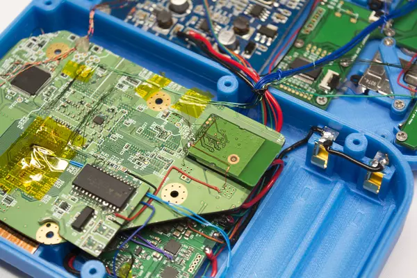
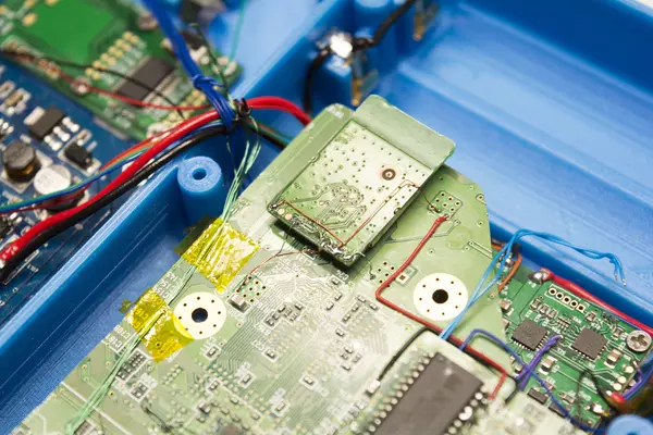
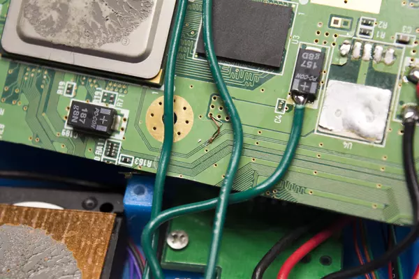
G-Boy Rev 3
Introduction
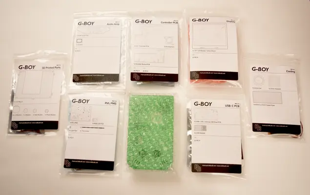
Included with the kit is everything you need to turn your Wii into a G-Boy save for a handful of things:
- A stock Wii console
- NOTE: The Wii console MUST be a RVL-CPU-40 or newer revision. Please check the Revision Guide on the BitBuilt Forums to check if your Wii will work for the G-Boy here: Wii Revision Identification Guide
- 2 - 3.7V 18650 lithium-ion battery cells
- A microSD card
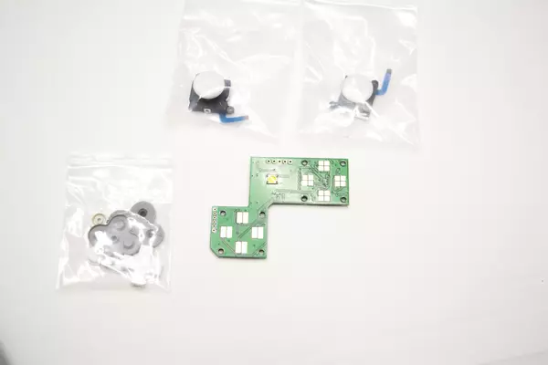
- NDSL A, B, X and Y buttons along with the D-pad and their respective membranes
- The required tools such as soldering iron, screwdrivers, etc.
Preparing Your Wii
The Wii destined to for use in your G-Boy must be trimmed. We recommend following the OMGWTF Trim Guide before continuing the G-Boy Rev 3 guide. Following the guide from start to finish is very important as it details both the software installation as well as the hardware modifications necessary before G-Boy assembly can be started.
NOTE: The Wii console MUST be a RVL-CPU-40 or newer revision. Please check the Revision Guide on the BitBuilt Forums to check if your Wii will work for the G-Boy here: Wii Revision Identification Guide
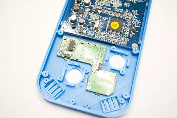
Installing the Shoulder Button Assembly
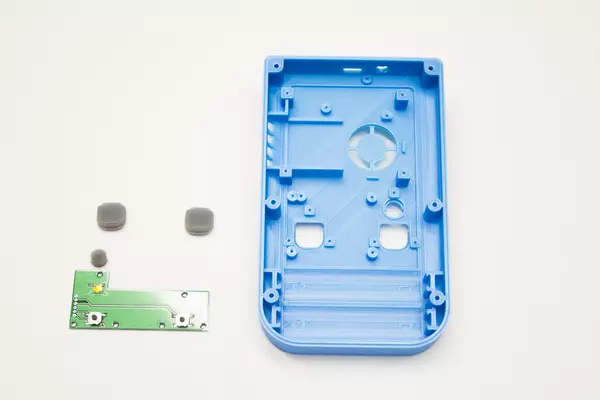
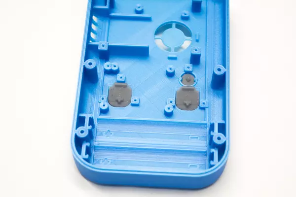
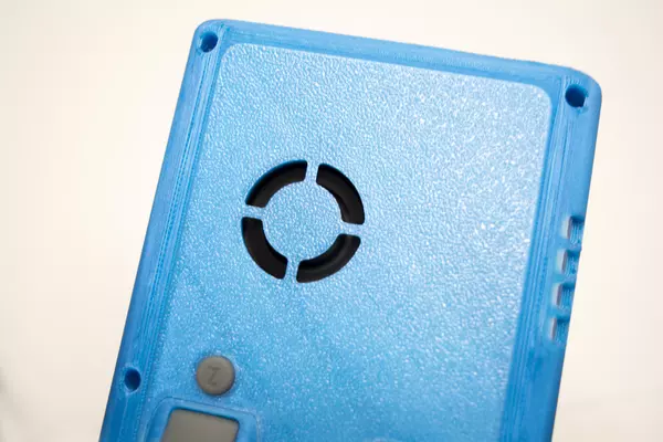
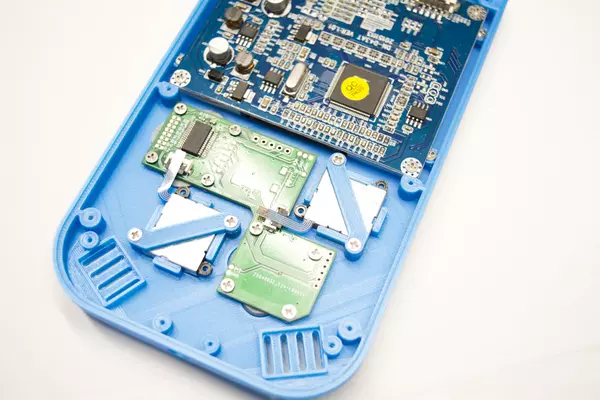
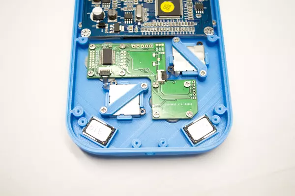
- Place each of the shoulder buttons and the Z button in the back of the case as shown.
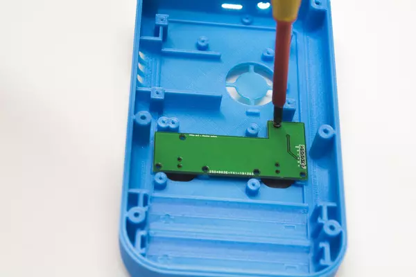
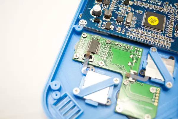
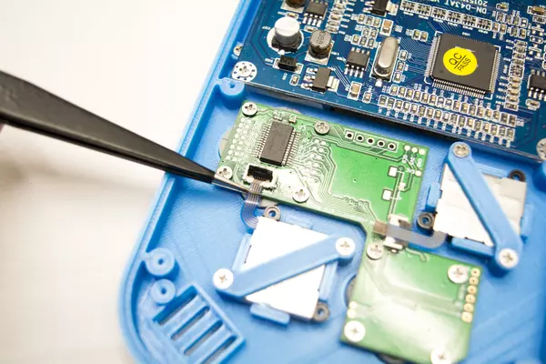
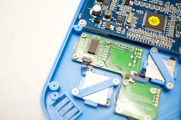
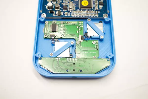
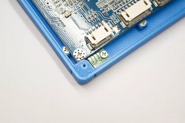
- Place the shoulder button PCB on top of the buttons previously inserted in the case, making note to align the PCB's mounting holes with the case's screw posts to properly align it.
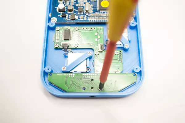
- Once you're sure of the position of the PCB take one M2x4 screw and, using a bit of force for the first few rotations, drive the screw into the back housing. Be careful not to over tighten, as the threads can be stripped on the housing.
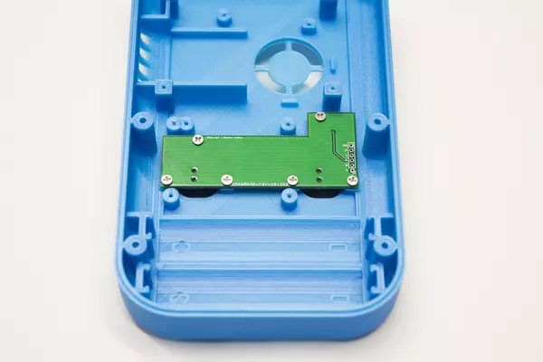
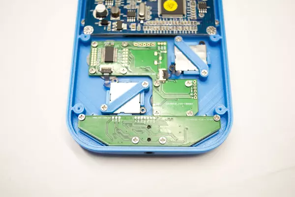
- Repeat for all 5 remaining mounting holes until the PCB is secured by the 6 M2x4 screws set aside earlier.
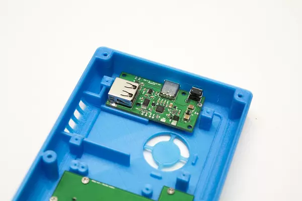
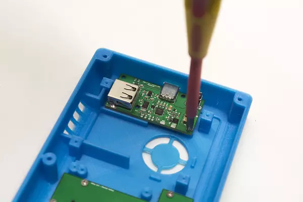
Installing the USB-C PCB & Power Button
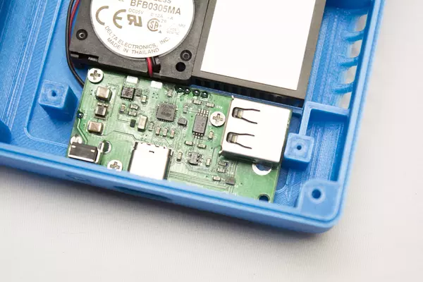
Once you're happy with the way the power button feels it's time to secure the USB-C PD PCB to the back housing.
- Grab 3 M2x4 screws from the parts bag labeled "Hardware" and secure them as displayed in the 3rd photo.
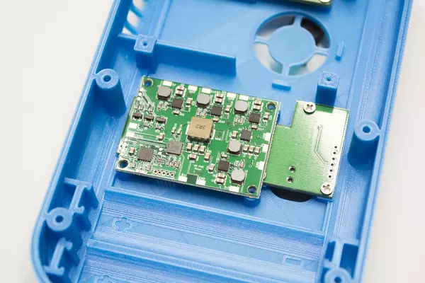
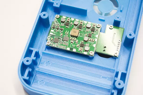
Mounting the Power Management System (PMS)
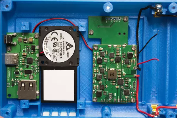
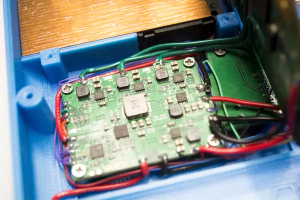
- Position the PMS PCB as shown in the provided image, ensuring its orientation is correct.
- Secure the PCB using the 4 M2x4 screws we grabbed earlier. Don't over-thread the screws as the threads can break if too much force is applied.
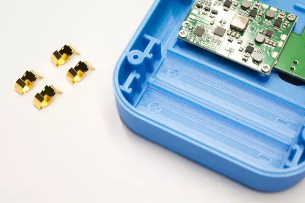
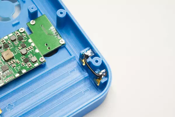
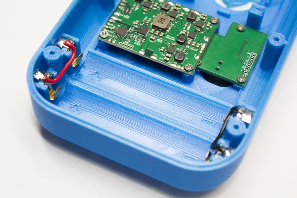
Installing the Battery Clips
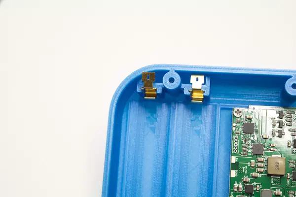
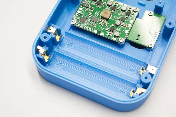
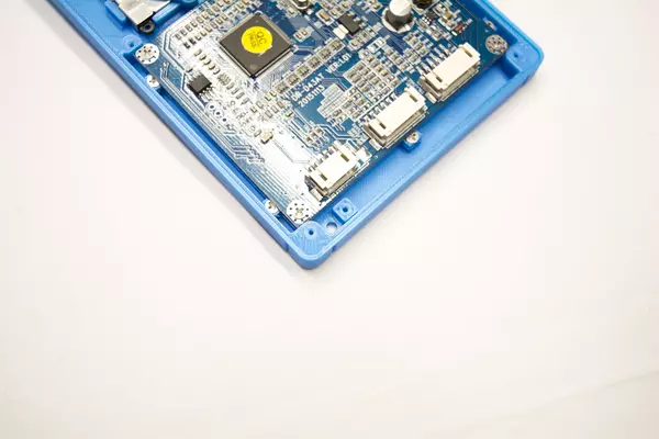
- Remove the four clips from the parts bag
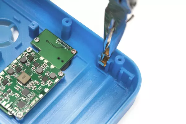
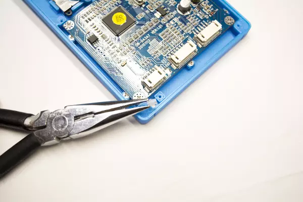
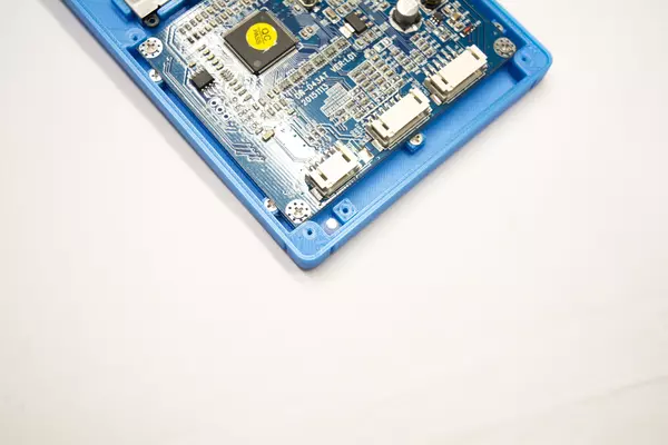
- Insert 2 of the clips in the top-most slots, as shown in the 2nd image
- If you're having difficulty inserting the clips, use a pair of pliers to assist grabbing them while inserting
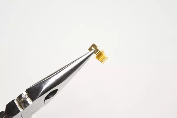
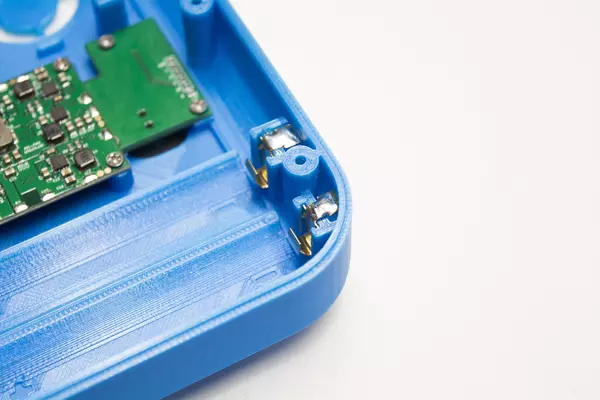
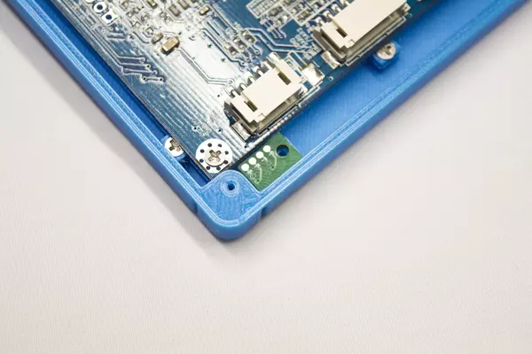
- The 2 bottom clips will require a slight modification to fit
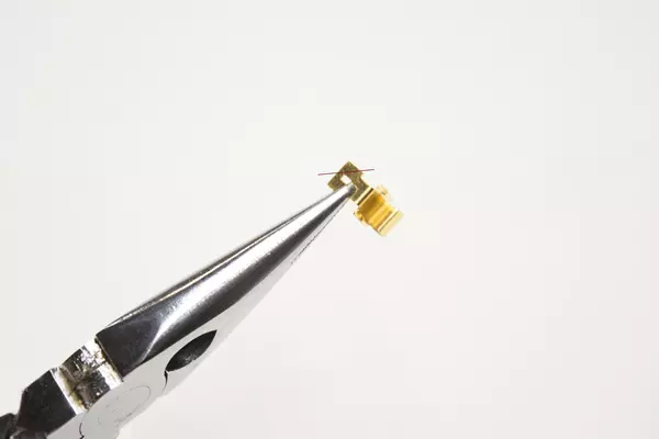
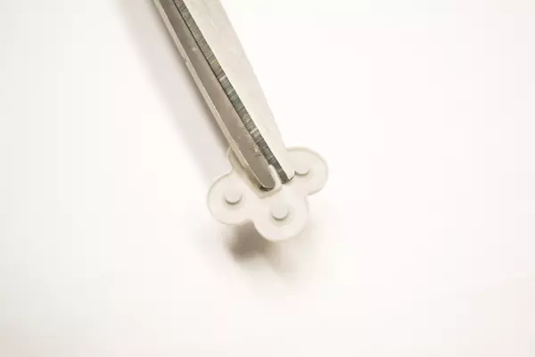
- Use a 2 pairs of pliers to slightly bend the corner of the battery clips so they no longer make contact with the G-Boy shell
- You may alternatively hold the clips with a set of pliers and then cut the excess off with snips
- Insert the remaining 2 clips in the bottom slots
Wiring the Battery Clips
- Hold your soldering iron on the clip you're tinning for a moment. CAUTION: Holding your soldering iron too long on these clips will melt your housing plastic!
- Feed the solder onto the clip. As long as your iron is hot enough, the solder should flow onto the clip and begin pooling on top.
- Once you've got enough solder (use the images for reference) on the clip you can move onto the next one.
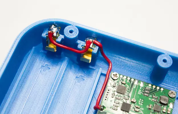
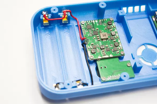
- Start by cutting two small lengths of wire, one for each set of battery clips.
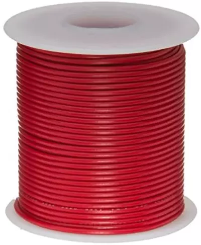
- Color is up to your preference, however this guide uses red and black wires to signify B+ and GND (Ground) respectively.
- Strip and tin your wire and solder it to one of the clips.
- You can bend the wire to a 90 degree angle after attaching it to the clips as shown in the images to prevent excess from getting in the way.
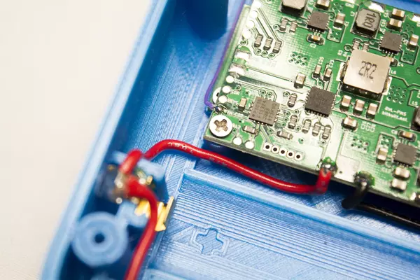
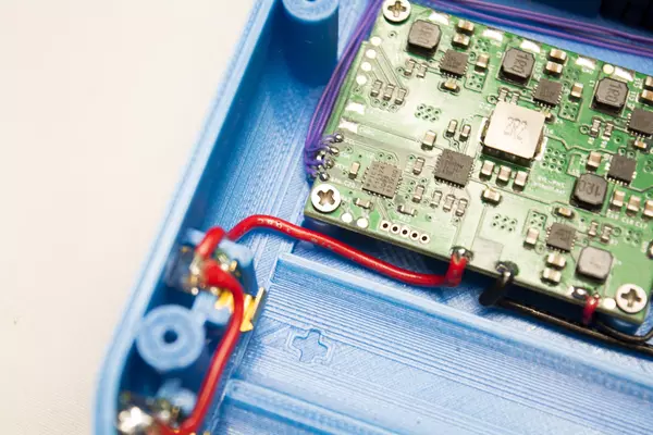
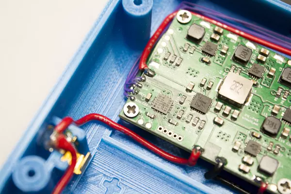
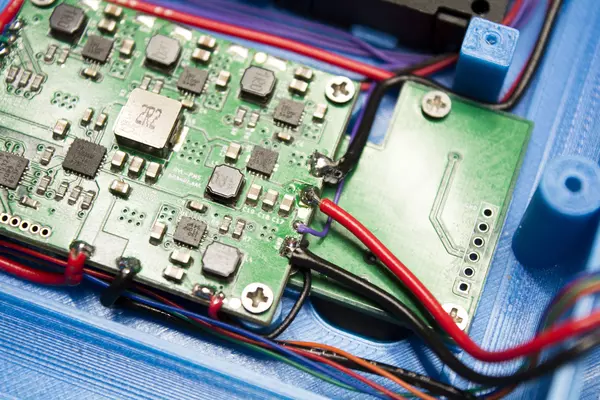
- Using your soldering iron, tin the B+ and GND pads on the PMS as shown in the image.
- Cut another small section of 22 AWG wire and tin one end of it. Solder it to the top B+ battery clip, and then route the wire as shown in the image.
- Once it's near the B+ pad on the PMS, trim off any excess wire and strip the end.
- Tin the newly exposed wire and solder it to the B+ like in the provided image.
Installing the Heatsink and Fan
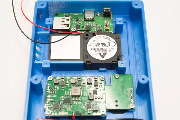
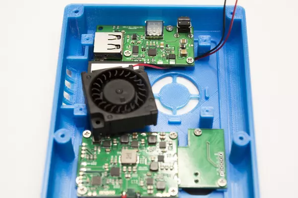
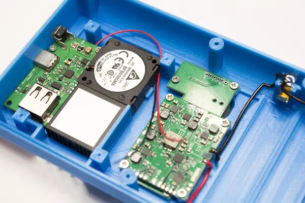
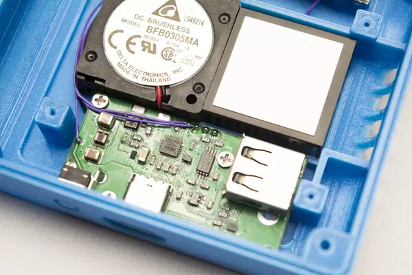
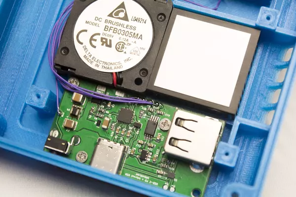
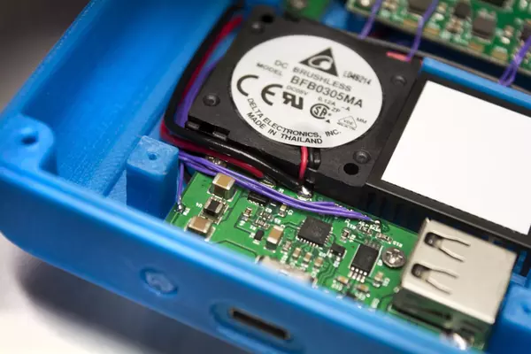
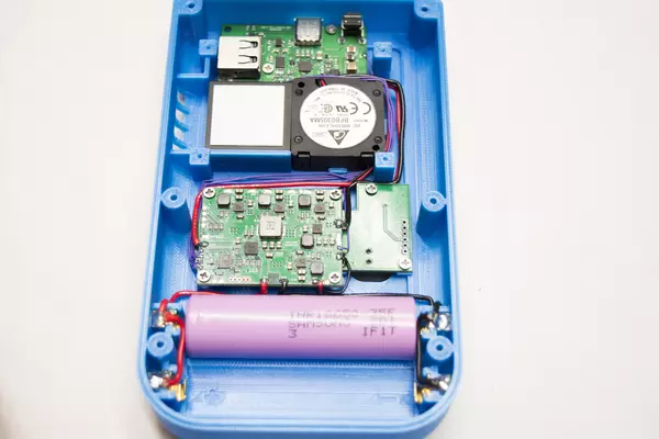
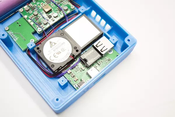
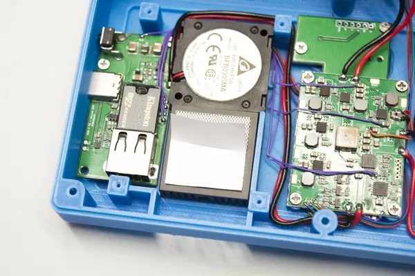
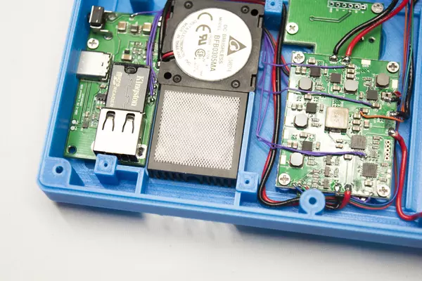
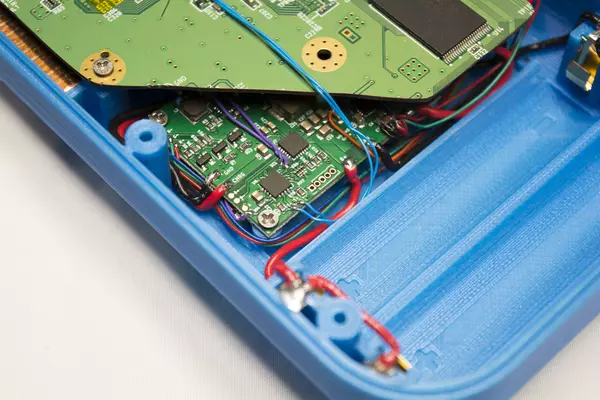
- Feed the wire underneath the mounted USB-C PCB. Ensure that it comes out between the screw post for the USB-C PCB and taller square screw post used for holding the Wii board in place.
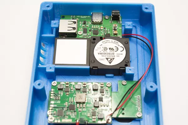
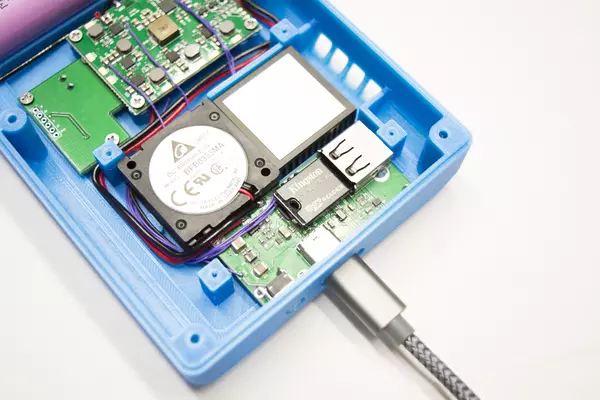
- Once the wires are routed through that spot, place the fan down. Make sure you pull the wires tight as slack can be pinched under the fan when placing it down! You'll notice towards the bottom of the fan next to the bottom right square screw post there's a gap where we'll be routing a few wires throughout the next few steps. Run your fan wires through this gap.
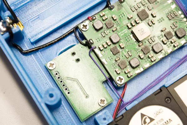
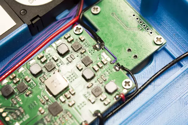
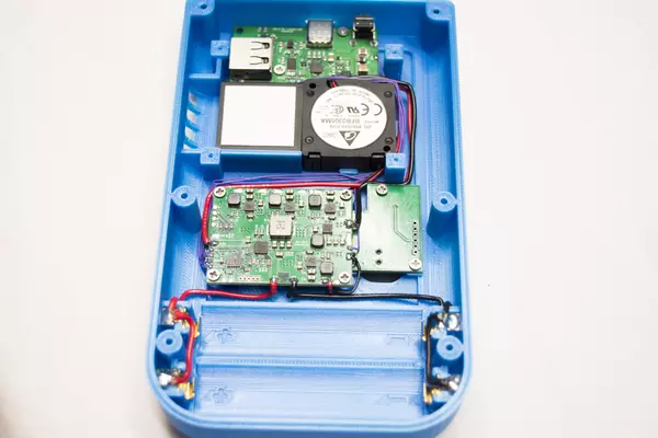
- Feed the wires underneath of the PMS but on top of the shoulder button PCB. This can be a bit tricky to do as the spacing is a bit tight, but as long as you're careful and don't bend the wires they should pass through on the bottom near where the batteries sit.
Wiring the Fan
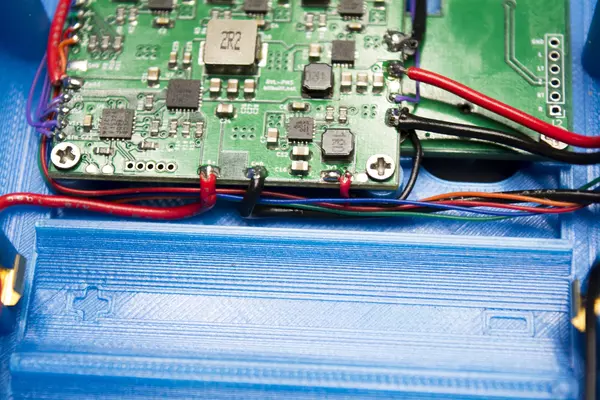
With the fan's power and ground wires poking out near the bottom of the PMS, you can pull them to size and cut any excess off. Strip the end of both wires off and tin each. Solder the red wire to either of the round pads next to the big 3.3V pad on the PMS. Make sure to tin whichever pad you're going to use before soldering the wire to it. The black wire can be soldered to any ground pad on the PMS.
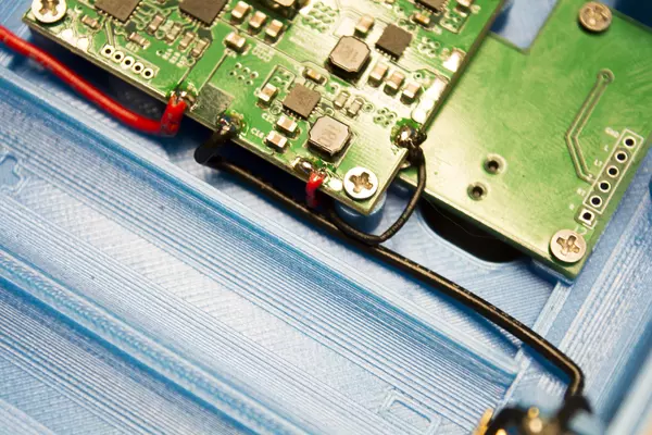
Wiring the Power Button
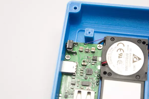
- Tin all pads on the USB-C PCB - we will be soldering to all of them in this section of the guide.
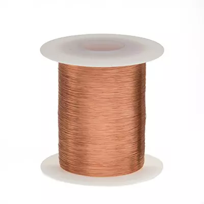
- Once you're done, grab some thin magnet wire and solder one end of it to the BTN pad on the USB-C PCB.
- Then, route it the same way we previously routed the fan power and ground wires. However this time ensure that the wire comes out along the left-hand side of the PMS, next to the corresponding BTN pad on the PMS PCB.
- When you're done routing, trim any excess wire off and solder the other end of the wire to the BTN pad on the PMS.
Wiring the I²C & Voltage Lines Between the PMS and USB-C PD Board
In order to communicate with the PMS to configure the USB Power Delivery, or PD which we'll refer to it as, and charge the G-Boy, the USB-C PCB must have the I²C pads wired to the PMS. Namely, these pads are SDA and SCL. We'll also need to run 5V and VSYS to the USB-C PCB so that the G-Boy can supply voltage the USB drive even when powered down.
- Using more magnet wire, attach a wire to both the SDA and SCL pads as well as the 5V and VSYS pads..
- Route them the same way we routed the BTN wire as well as the fan power wires.
- Once the wires are routed near the PMS, attach them as shown. Ensure that the wires are soldered to the correct pads as charging will not work with SDA/SCL inverted.
- TIP: Use two different colored wires to keep track of which line is which!
- Solder the 5V wire to one of the small round pads next to the bigger 5V pad as shown in the image.
Connecting the PMS and USB-C PD Charging Voltage Lines
The last two wires we need to solder between the USB-C PCB and the PMS are the charging wire and a ground wire. For both of these lines, use the same type of wire you used for wiring up the battery clips to the PMS.
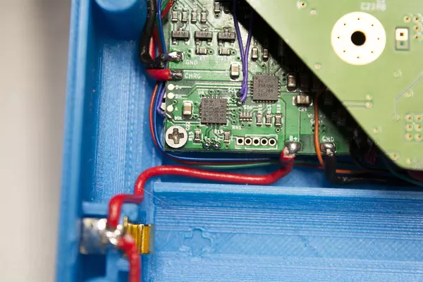
- Strip, tin, and solder the wires to the USB-C PCB as shown in the image.
- Route it around the square screw posts used for the Wii, and then around the USB-C wiring from the previous steps. If you have tweezers, you can pull the wire to form 90 degree bends in order to make the routing neater.
- Trim off any excess wire once you reach the CHRG and GND pads on the PMS PCB, then strip, tin, and solder the wires to the PMS.
Testing the PMS
Testing the USB-C Board Wiring
- Use a multimeter to make sure the RVL-PMS turned on by probing any of the voltage pads to see if they're giving off the correct voltage.
- Use a multimeter to check to make sure that your ground wire is connected properly to the USB-C PD PCB. The power button requires ground in order to turn the G-Boy on.
- Measure the battery with a multimeter to ensure it's charged enough to power the RVL-PMS. If it's lower than 3.4-3.5V it will need to be charged before use.
Preparing the LCD
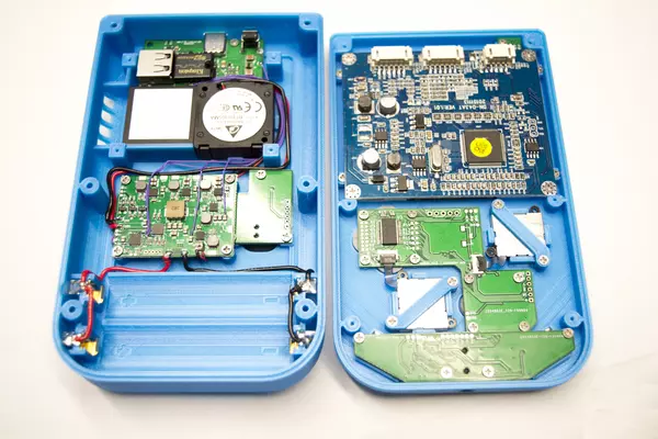
With the back half of the G-Boy wired up, we can set is aside as we'll be focusing on the front half of the assembly, starting with the LCD.
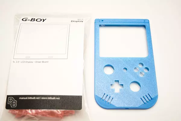
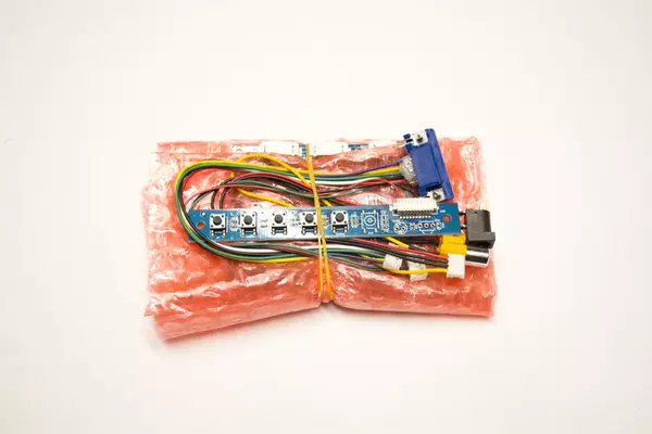
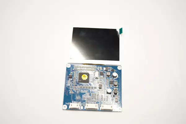
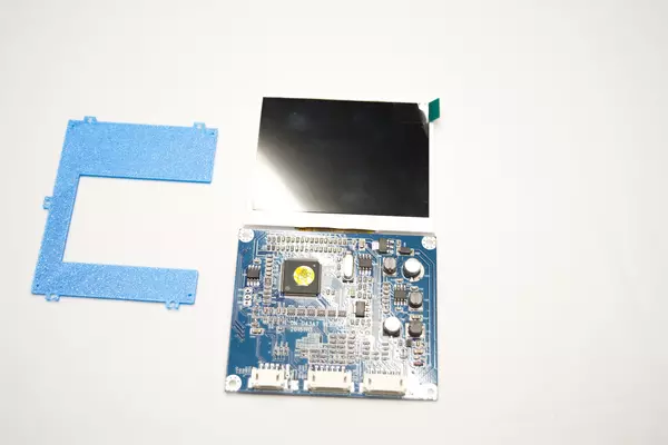
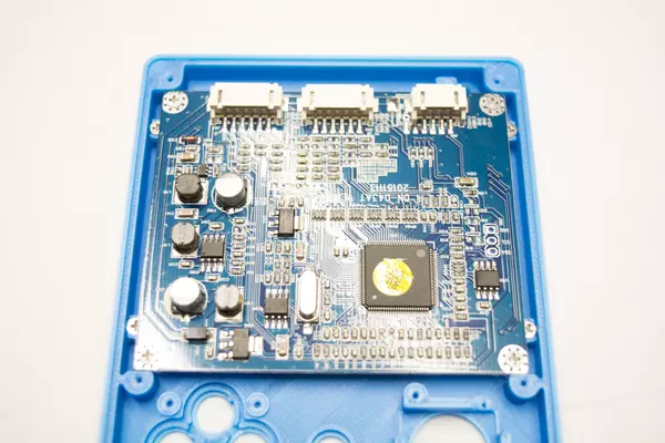
- From the Display bag, take out the entire LCD package. It contains the LCD attached to the driver board, along with a controller PCB for the screen and two cable sets. There is also two sets of LCD bezel decals. We will apply one to the LCD module later.
- We'll only need the LCD & bezel decal of your choosing for now, so the rest can be set aside.
Modifying the LCD Driver Board for 5V
The LCD driver board that comes with the G-Boy kit needs to be modified to run off of 5V by removing a single component, an inductor. If you own a hot air station, you can easily remove it by using that tool. Otherwise, watch this short video on removing the inductor using only a soldering iron.
Applying the Screen Bezel Decal
Watch this quick video to install the screen bezel. Be sure to choose your color wisely as getting back to the LCD once the G-Boy is assembled can be difficult!
Mounting the LCD
From the parts bag labeled "3D Printed Parts" grab the LCD mounting bracket. Also, from the parts bag labeled "Hardware" grab 9 M2x4 screws.
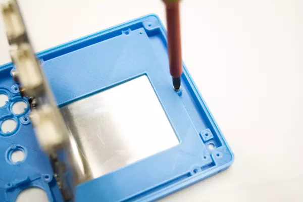
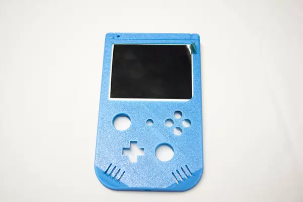
- First place the LCD down inside of the G-Boy front case. Be sure to stick the peel tab on the screen protector outside of the G-Boy case so it's easy to peel off after the assembly is complete.
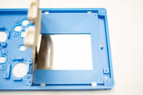
- Grab the mounting bracket and place it as shown in the image. Make sure it's facing the right orientation. The textured side should be facing the LCD. Be mindful of the flex cable attaching the LCD to the driver board.
- Using your M2x4 screws, secure the bracket to the screw posts.
- Once you have all 5 screws in place, lay the driver board back down.
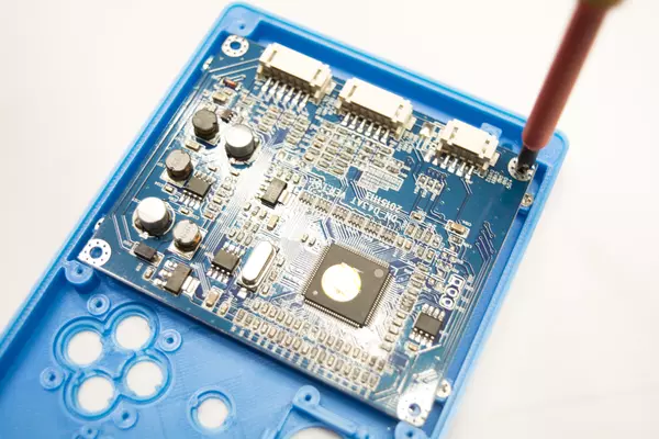
Notice there are 4 screw posts in the corners of the LCD mounting bracket. These screw posts are used to secure the LCD driver board to the bracket.
- Using your 4 remaining M2x4 screws, fasten the driver board to the bracket.
- Once the driver board is in place the section is complete!
Test Fitting the Face Buttons
Take out the following items:
- The remaining items out of the parts bag labeled "Controller PCB"
- Your self-provided DS Lite buttons and membranes
- The start button from the bag labeled "3D Printed Parts"
- 8 M2x4 screws from the bag labeled "Hardware"
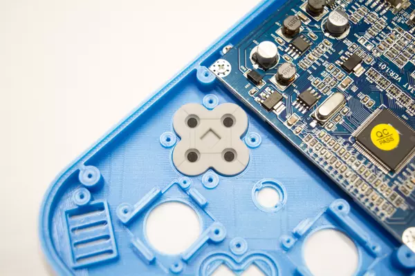
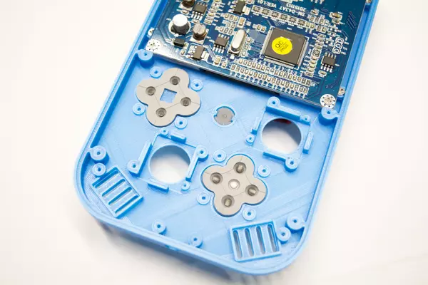
- Insert the A, B, X and Y buttons into their respective slots along with the D-pad and the start button.
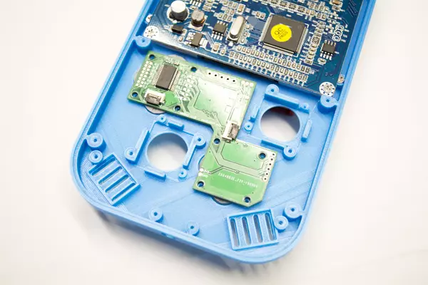
- Place the respective membranes over their buttons, and place the controller PCB over top.
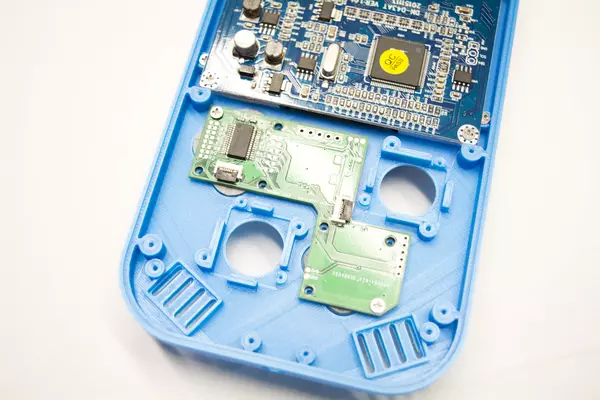
- Use 2 of your M2x4 screws to secure the PCB from 2 screw posts diagonally opposite of each other as shown in the secondary image provided.
- Use this opportunity to test the feel of the buttons in the case. Make sure to hit the face buttons from multiple angles as well to ensure that they do not stick
Modifying the Button Retainers
As there are many different reproduction NDSL buttons available online, some of them come from different sources and may not fit exactly right inside of the G-Boy shell. The front casing can be modified very slightly to fix any sort of sticking button or hard to press issues you might encounter with NDSL buttons from different sources. A short video that will help you fix any and all issues you might have can be viewed on the left.
Securing the Front Button PCB
Once you are happy with the way your buttons feel, you can continue to screw in the rest of the M2x4 screws required to fully secure the controller PCB to the front half of the G-Boy.
Securing the Analog Sticks
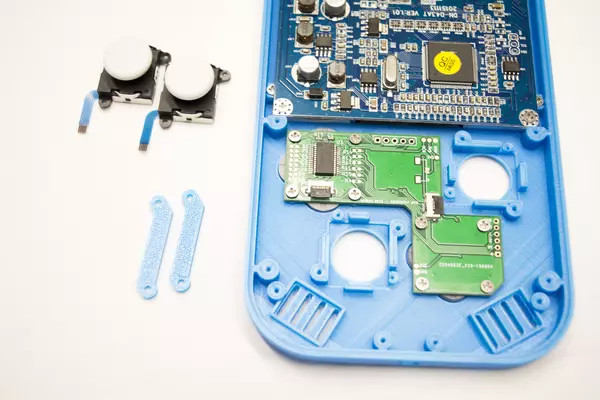
From the bag labeled "3D Printed Parts" grab out both of the analog stick mounts. Also from the bag labeled "Hardware" grab out 4 M2x4 screws.
- Remove your analog sticks from the plastic bags they arrive in.
- Place one into the front casing as shown in the picture.
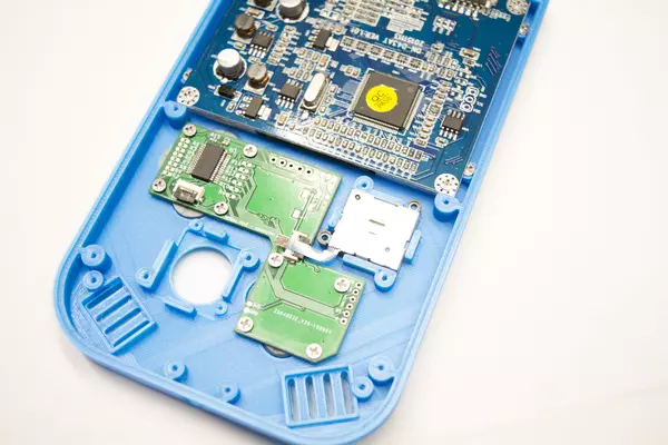
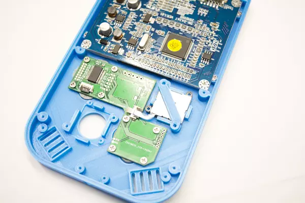
- Take one of the crossbar mounts and one of the M2x4 screws.
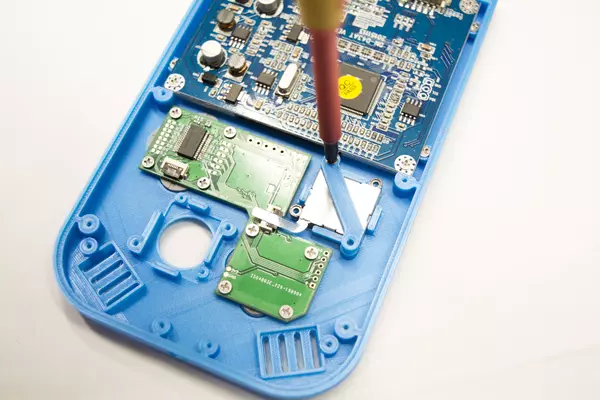
- Place the mount in the correct orientation and use the screw to fasten the mount to the casing.
- Once you're done, rotate the mount over top of the other screw post and secure it as well.
- Repeat the process for the remaining analog
stick.
Connecting the Analog Sticks to the Controller PCB
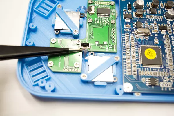
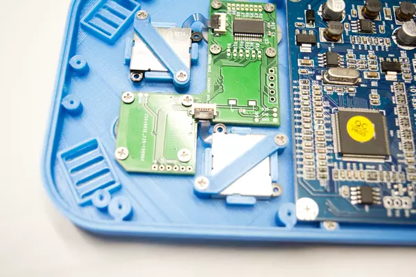
- Using a small pair of tweezers, plastic spudger, or another small hand tool carefully open the FFC connectors on the controller PCB by pressing up on the black tab from underneath.
- Using tweezers, insert the cables connected to the analog sticks into the connectors.
- Gently push the cables into the connectors until they don't go in any further. You do not want to damage the cables by being too rough!
- Close each black tab by pressing down on it until it clicks closed.
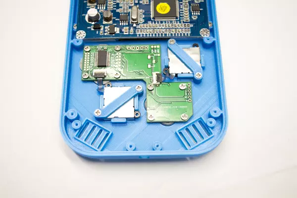
- Once both sticks are connected to the controller PCB, this section is complete!
Inserting the Speakers
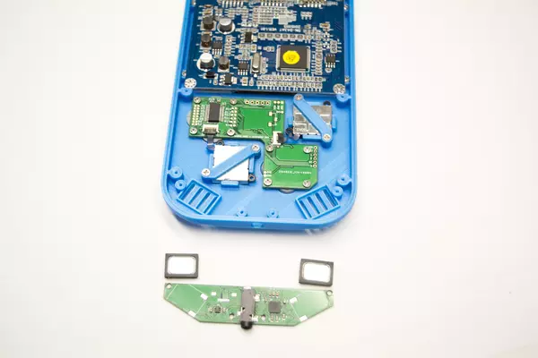
- From the bag labeled "Audio Amp" take out both the amp PCB and the speakers.
- Then, place the speakers into the front casing with the pins facing down as shown in the provided image.
Installing the Audio Amplifier PCB
- Using the M2x4 screws, secure the audio amp PCB to the front casing.
- After you've fastened all 4 screws, this section is complete!
Inserting the RGB LED Light Pipe
Included in the bag labeled "RVL PMS" contains another bag which has the RGB LED PCB and light pipe inside. Grab both of these parts along with 1 M2x4 screw from the bag labeled "Hardware".
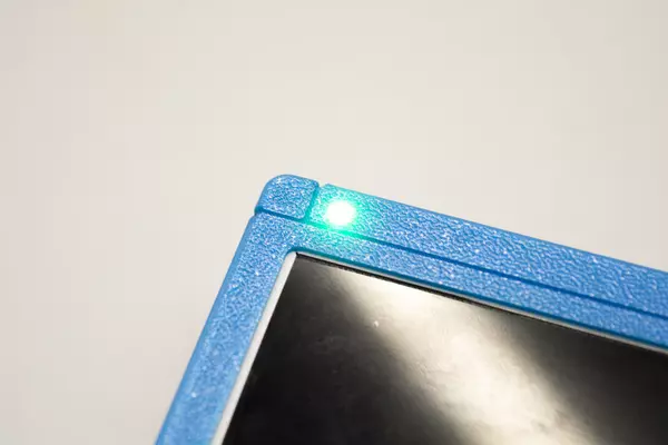
- Lightly grab the light pipe using a pair of pliers and insert it into the hole for it near the top of the front casing. The long end goes into the hole.
- Once you have the light pipe inserted, flip the casing over and check to make sure it's inserted all the way. The light pipe should be nearly flush with front housing of the G-Boy.
- If you think yours is too low, close the pliers and press on the back of the light pipe. Sometimes it will "click" into place once it's fully in place.
Securing the RGB LED PCB
- Once you're satisfied with your light pipe positioning, take the RGB LED PCB and the M2x4 screw you set aside earlier and place the RGB LED PCB over top of the light pipe and screw post.
- Use the M2x4 screw to secure the PCB to the front half of the case.
- After it's secure this section is complete!
Wiring 5V to the LCD Driver Board
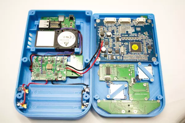
As mentioned earlier in the guide, we will be using the 5V pad on the RVL PMS to power the LCD driver board.
- Using the same type of 22 AWG wire you used for the battery clips, cut two wires; one for 5V and one for GND (Ground).
- Solder one end to the RVL-PMS as shown in the image.
- Next, route the wires as shown in the images. Once you run it to where we removed the indcutor, trim the 5V wire, then strip it and tin it.
- Next, tin the top pad of the inductor footprint and solder the 5V wire to this pad.
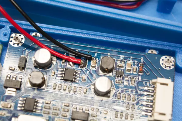
- For the GND wire we will be soldering it to the capacitor (C147) right above the 5V pad as shown in the fourth image. You might need to add some solder to the capacitor in order to solder the wire.
- Once both your 5V and GND wires are secure on the LCD's driver board, you can move on to the next step.
Wiring the RGB LED PCB to the PMS
Grab the magnet wire that you used earlier on the USB-C PCB wiring for this step.
- Tin the R, G, B, and VSYS pads on the PMS PCB and all 4 of the pads on the RGB LED PCB.
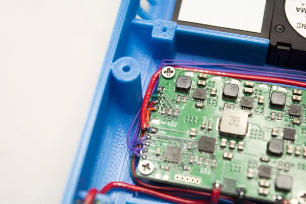
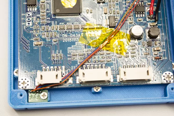
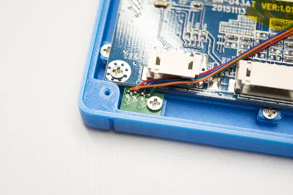
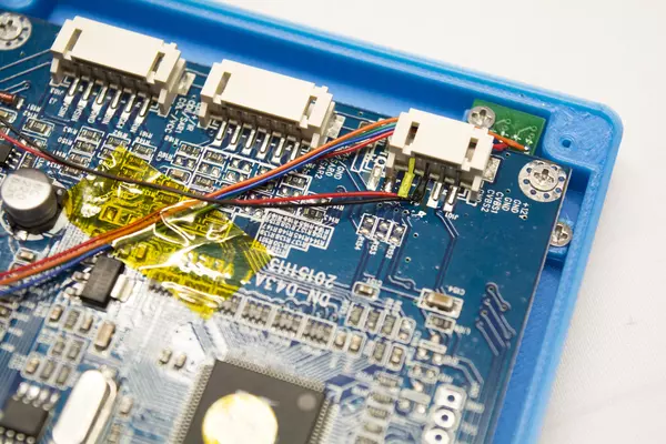
- Next, solder a wire to each of the R, G, B, and VSYS pads. As shown in the provided images, the color of the wire corresponds with each pad; red(R), green(G), and blue(B). VSYS is the orange wire.
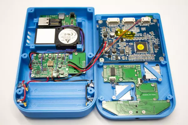
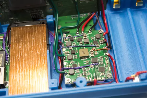
- Route these wires underneath of the wires going to the battery clips as shown.
- Solder each wire to their respective pads on the RGB LED PCB.
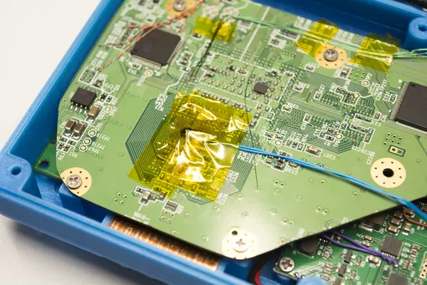
- Once you're done, secure the stretch of wire to the driver board with a small piece of tape. In this instance, we've used kapton tape as it's thin, clear, and non-conductive.
Power System Testing and Verification
Before we move on to another section, it's important to first make sure that your wiring is correct and working.
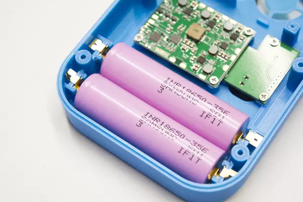
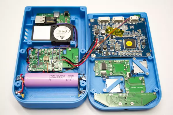
- Begin by placing one of your 18650 cells into the G-Boy. Like last time, always double check with a multimeter beforehand to make sure you connect it properly.
- Hold down the power button for a couple of seconds to turn the unit on as we previously did.
If your wiring is good then the RGB LED should turn on! Double tap the power button and it should switch modes. Here is a quick rundown of the three different modes:
- RGB Fade: This mode fades the LED through many different colors.
- Battery Status: This mode displays a color that corresponds with the current charge status of your G-Boy.
- Green - Fully Charged
- Yellow - ~50%
- Red - <20% remaining
- Shipping Mode: This mode will permanently turn off your G-Boy until a charger is plugged in. This is to prevent the unit from coming on if the button is accidentally pressed while it's enclosed.
Preparation for Wiring the Wii Motherboard
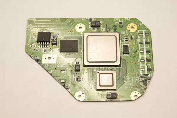
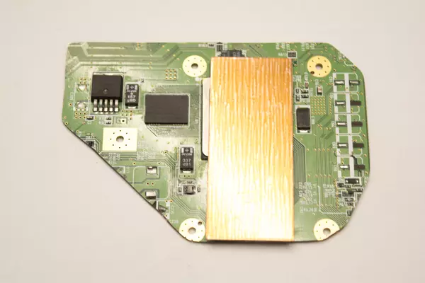
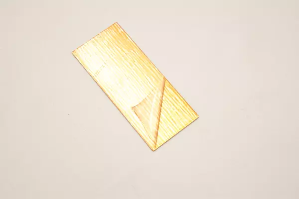
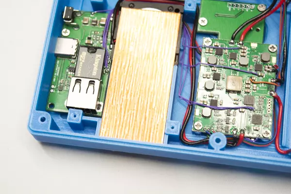
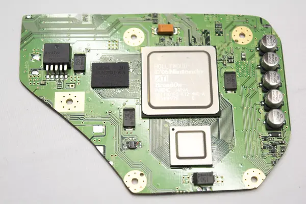
- Before you do that though, you'll need to remove the plastic covering the adhesive material on the heat sink and stick down the copper plate found in the "Cooling" parts bag.
- Make sure that you remove the plastic covering from the copper plate before sticking it down.
Wiring PMS Voltage to the Wii
Use the same 22 AWG wire you used for connecting the battery clips for rewiring all the lines in this step:
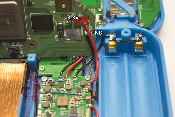
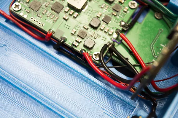
- Solder 3.3V and GND to the points shown (Red and black wire, respectively)
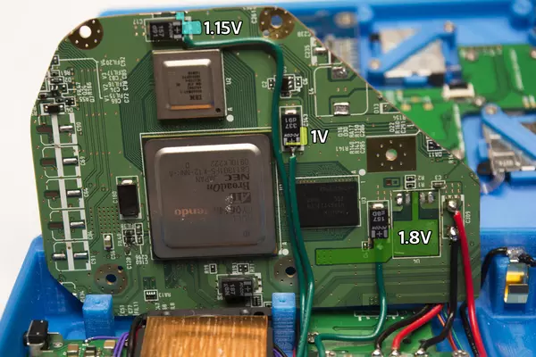
- Solder a wire between the 1V, 1.15V, and 1.8V relocation points shown in the image and their complimentary pads on the RVL PMS.
- Ensure your wires have enough room to bend. They'll move a bit when you fold the Wii motherboard back into place.
Wiring Composite Video to the Screen
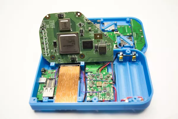
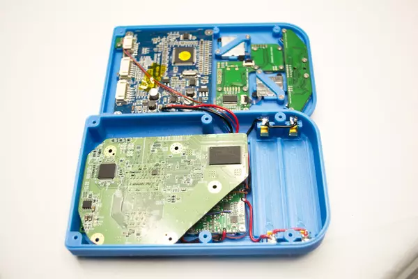
- Fold the Wii motherboard back down as shown.
- We will not screw the motherboard down yet as there are other steps that require access to the front of the board.
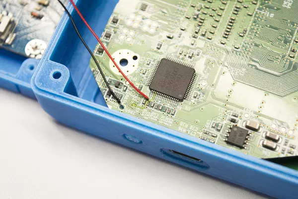
- Using 30 AWG wire, solder a wire to composite video (highlighted in yellow) and ground (black) as shown.
- Solder the wire to the points displayed on the LCD driver board.
Wiring USB
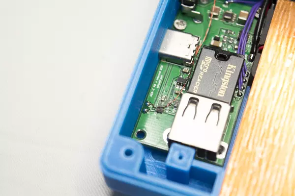
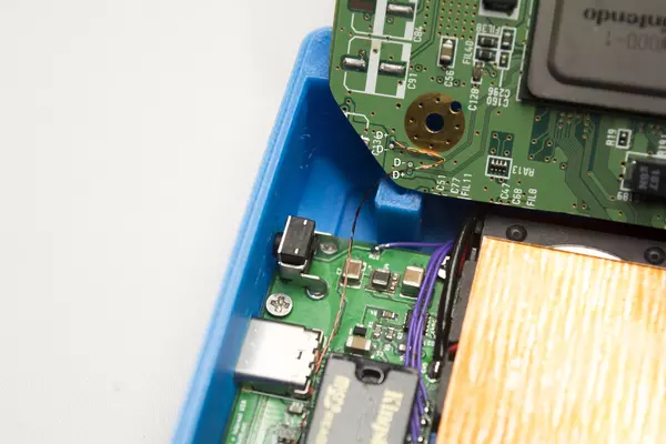
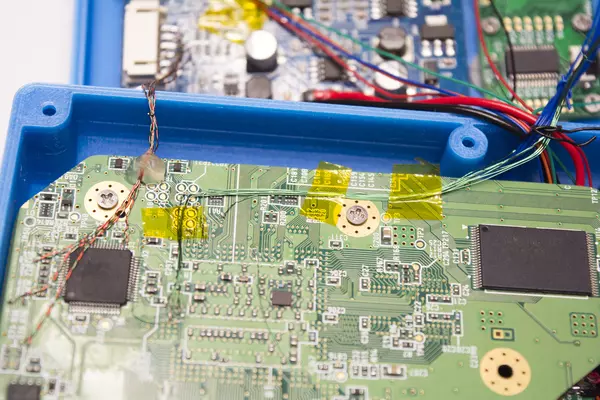
Using 34 AWG magnet wire twisted together with a drill (see example here) we're going to need to wire the USB D+ and D- lines between the Wii and the USB-C PCB.
- Blob a large amount of solder on the tip of your iron and move your twisted wire ends through the blob to strip the magnet wire.
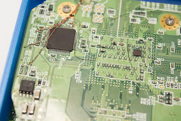
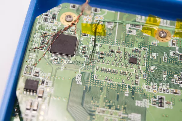
- Solder the two wires to the vias on the Wii as shown.
- TIP: If you don't have multiple colors of wires, you can mark both ends of a single wire, or only tin one of them at the start.
- Trim the wire to the length of the distance of the D+/D- pads plus a little slack for routing.
- Solder the other end of the wires to their respective data pads on the USB-C PCB.
Testing the Trim outputs Video
- Insert a single cell and power on the G-Boy.
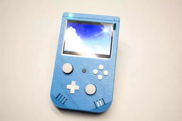
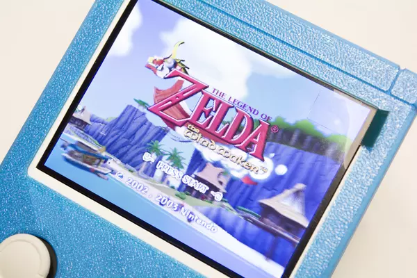
- If your Wii boots up and you see video on the screen then great! Your trim works. You're ready to move onto the next section.
- If you get no video then try some of the troubleshooting tips below.
- Make sure you have a ground wire going from the Wii to the driver board near your video line as shown.
- Attach the controller board included with the LCD to the middle connector on the driver board. Press the source button while the G-Boy is powered on to ensure the LCD did not ship in VGA mode.
If you do not plan on performing the Bluetooth module relocation, you can use 4 of the M2x5 screws to screw the motherboard to the back half of the case. Ensure you apply some sort of thermal paste onto both the CPU and GPU of the Wii before screwing it down.
Wiring the GC+ PCB
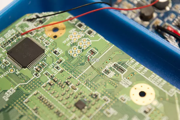
In order to get the controller working on the G-Boy, we need to run a data wire between the controller PCB and the Wii motherboard along with a voltage and ground wire in order to provide power to the controller board.
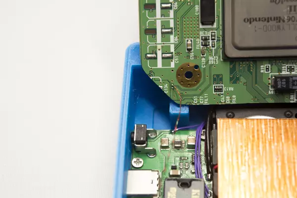
- Solder one end of magnet wire to the via as shown.
- Solder a wire to the second round 3.3V pad on the PMS, as well as one to a ground pad as shown.
- Route the wires down along the LCD power wires and controller PCB power wires.
- Trim and tin the magnet wire and solder it to the "GCD" pad on the controller PCB. Solder the 3.3V wire to the pad labeled "3V3" and the ground wire to the "GND" pad.
Wiring the Shoulder Button PCB
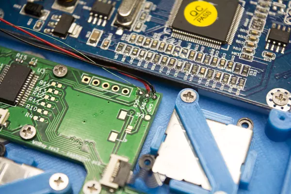
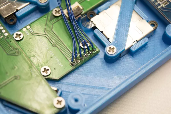
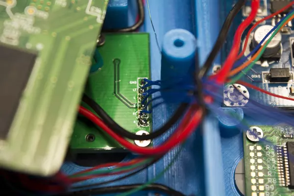
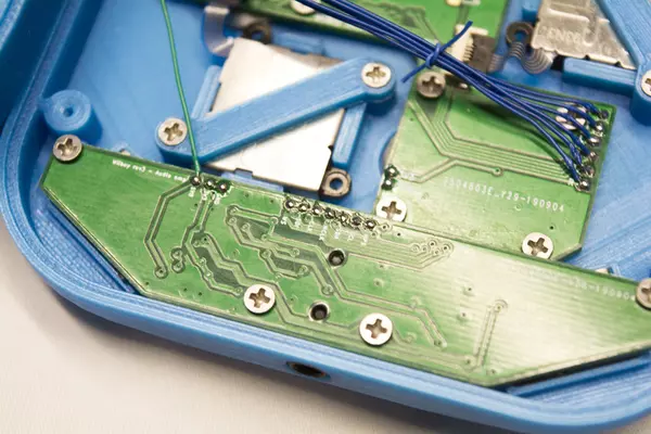
In order to get the L, R & Z buttons working we'll need to connect the shoulder button PCB we inserted in the back housing earlier to the controller PCB by soldering wires between them.
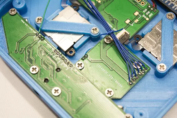
- First tin each of the pads on both PCBs. You may need to move the Wii motherboard out of the way as shown in order to reach the shoulder button PCB with your soldering iron.
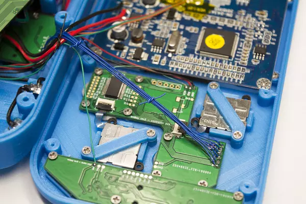
- Using 30 AWG wire, solder a wire between each pad to the corresponding one on the other PCB.
- Ensure you use IPA with a toothbrush to clean where you've soldered. As seen in the image, tinning the pads leads to a lot of excess flux remaining on the board.
Once you've wired everything, put a cell into your G-Boy and test the buttons using the included GC+ 2.0 Configurator homebrew by selecting "Buttons test".
Wiring the VGA Data Lines
Using the twisted 34 AWG magnet wire we used to wire the USB lines, we will be wiring VGA to the LCD driver board.
- Twist and cut 4 lengths of magnet wire.
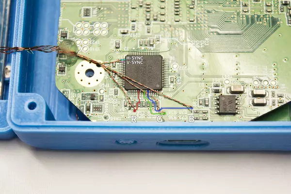
- Solder one wire to the R, G, and B channels as shown and the other to GND. Use a multimeter to verify GND points around the Wii motherboard if you're unsure of where to solder.
- Solder the remaining wire to the H/V sync pins on the video encoder as highlighted in the image. Ensure that the pins do not bridge.
- Run a wire from the mode via as shown, or the test point TP47 on the right-hand side of the video encoder, to 3.3V. Use a multimeter to verify 3.3V points around the Wii motherboard if you're unsure of where to solder.
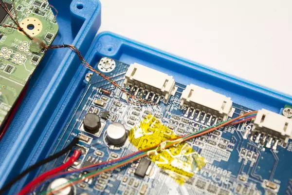
- Solder the other end of each of the wire pairs to their corresponding pins on the driver board PCB. You can solder each of the GND wires to the single GND pin.
- Use tape or a small blob of hot glue as shown in the image to route the wires. There is an inductor on the LCD driver board that can cause interference if the wires get too close.
Testing VGA Video
In order to test and verify that your wiring works, you'll need to grab the menu button PCB included with the display that we set aside earlier.
- Plug it into the middle connector on the driver board.
- When the G-Boy is powered on (hold the power button down for two seconds), press the "source" button to switch from composite video to VGA.
- If it pops up, go ahead and press the "Menu" button and once the OSD settings menu opens, use the menu button to navigate down to "Auto" and press the Up/Down button to auto adjust the image.
Preparing to Wire the Audio System
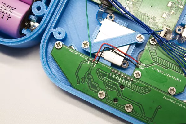
Wiring audio on your G-Boy is a difficult part of the assembly. You need to solder wires into 7 different vias on the Wii, some of them right next to each other. It's important to take your time and do this step carefully.
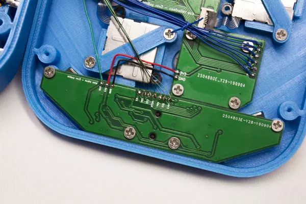
- Solder a magnet wire to the round pad next to the bigger 1.8V pad on the PMS and solder it to the 1.8V pad on the amplifier as shown.
- Tin the remaining pins on the amplifier PCB as shown.
- Also tin the 3.3V and GND pads shown in the image.
Wiring Audio Power
You'll need to solder the 3.3V and GND pins between these two boards in order to power the audio amplifier.
Wiring the Digital Audio Data Lines
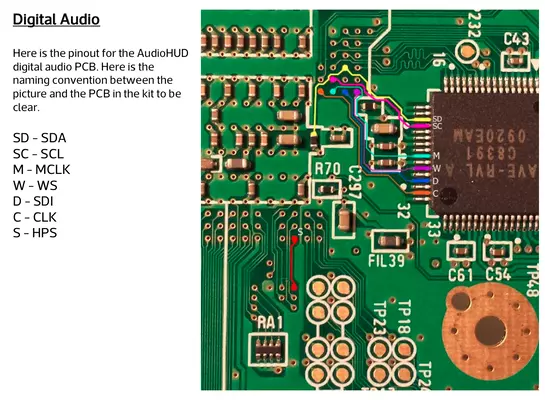
- Tin the vias as shown
- Solder a piece of magnet wire to each of the vias you just tinned. Solder the other end of each wire to their respective pads on the amplifier board as per the pinout.
- After soldering a wire into each of the vias shown in the pinout, you can route them as shown in the accompanying images.
- Use kapton tape to hold the wires down.
Tidying the Internals
Using the magnet wire or wrapping wire we can cut small sections and use it to neatly tie our wiring together.
- Cut a small section of wire.
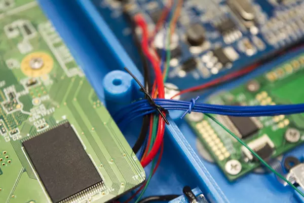
- Loop it around all the wiring you want to tie together and then make a knot using the wire.
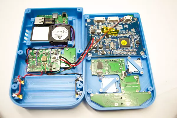
- We recommend making a tie around the wiring going between the two G-Boy housing halves, as well as one around the shoulder button wires if they aren't pulled tightly enough.
- It's also optional but you can use magnet wire to tie
together the VGA and audio wiring as well. See the VGA and Audio Wiring
sections for more pictures.
Connecting the Thermistor for Overheating Protection
Included in the parts bag labeled "RVL PMS" is a thermistor. This gets mounted on the Wii motherboard so that if G-Boy overheats due to being enclosed (ex. it's in a backpack and turns on because you forgot to put it in shipping mode) the RVL-PMS will power the G-Boy down automatically once it reaches 70°C.
- If you have any batteries in your G-Boy, remove them before proceeding.
- Tin the T+ and T- pads as shown.
- Attach the thermistor between the CPU and GPU as shown. We've held it in place using a few pieces of kapton tape.
- Route the wire down to the T+/T- pads. If the exposed wire is excessively long on the thermistor, trim them a bit.
- Solder the thermistor wires to the T+ and T- pads. Polarity does not matter, so solder any wire to any pad.
Testing the System Before Closing
Boot up your G-Boy and ensure the following items work before you proceed to the next step:
- Audio
- Have the courage to test the headphone jack
- VGA Video
- If some of your white colors appear purple, turn down the green channel through the LCD's settings menu
- Every button; Boot into the GC+ 2.0 Configurator homebrew app and select "Buttons Test"
- If the face button pressed are unsatisfactory, return to the "Mounting the Controls" section for more information on how to improve their feel.
- Charging (see the "parts" section of the step for our recommended charger and cable)
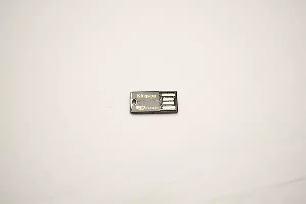
- Accessing your microSD through the USB-C port (plug your G-Boy into a computer)
- If you relocated the Bluetooth module and/or MX chip, make sure those work as well.
Closing the Case & Final Steps
Take out 6 M2x6 screws from the bag labeled "Hardware".
- Close the G-Boy and insert a screw into one of the screw holes on the back. Using a long phillips head screwdriver, hold the G-Boy closed and fasten the screw. You might need to add pressure for the first couple of rotations to ensure that the screw threads the screw post.
- Repeat this process for the remaining 5 screws.
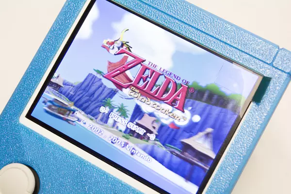
- Remove the screen protector and start playing some games!
(Optional) Relocating the MX Chip (1/3) - Prep & Mounting
The MX relocation will restore RTC (real-time clock) functionality to your G-Boy for use in titles such as Animal Crossing along with displaying the correct date on the saves that utilize this feature.
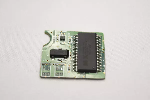
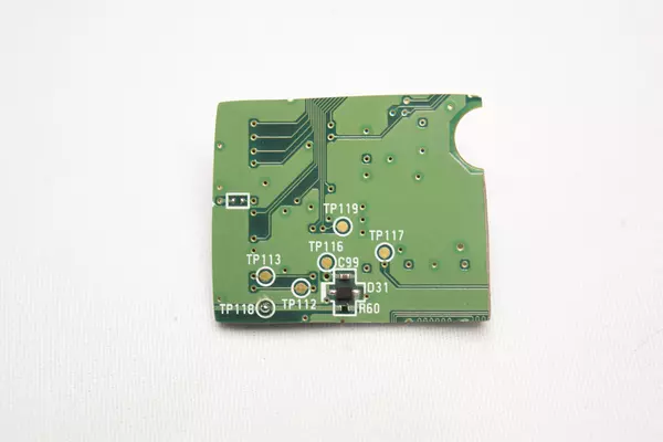
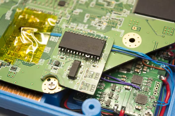
- Grab the MX section of the board that's trimmed in the trimming video present in the "OMGWTF Trim" manual.
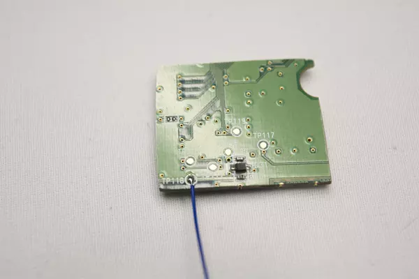
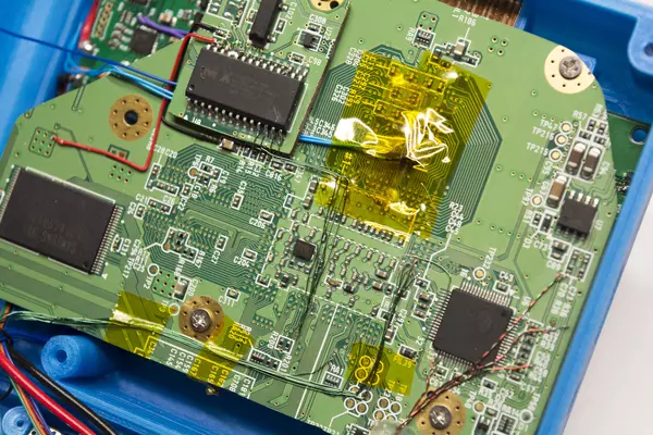
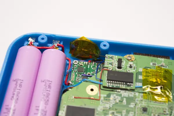
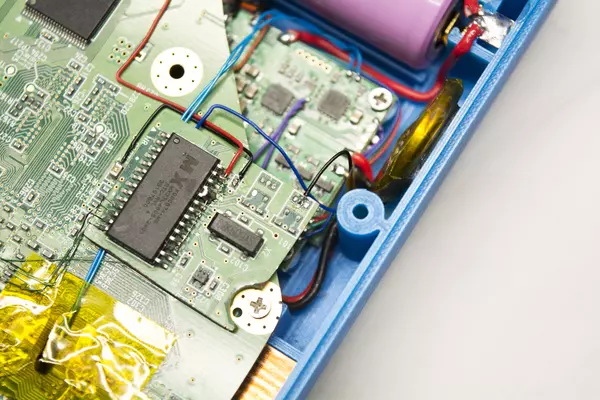
- Solder a wire for the coin cell to TP118 on the back of the board cutout.
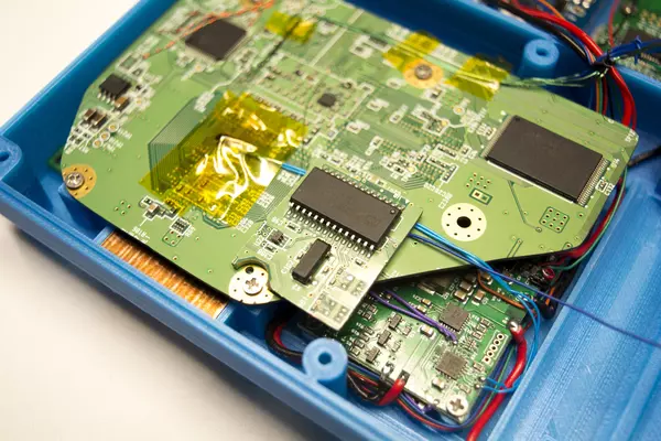
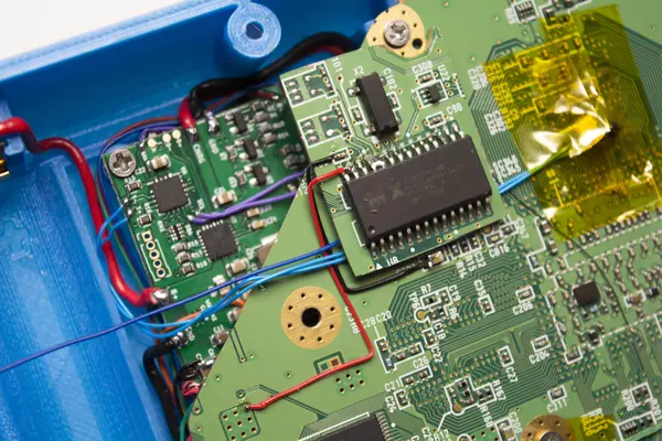
- Use a small drop of hot glue to mount the MX section as shown. We'll be attaching it here so that it does not hit on anything when we go to close the G-Boy.
- Once it's mounted, we'll need to connect the 4 3.3V pins on the chip as shown. We've used 34 AWG magnet wire in this instance.
(Optional) Relocating the MX Chip (2/3) - Wiring Power & Data
We'll need to wire 3.3V and GND to somewhere on the Wii board.
- Using magnet wire, solder 3.3V and GND between the MX chip and the Wii motherboard as shown.
- Using magnet wire, solder the 4 MX chip data pins to their respective vias on the Wii using these diagrams:
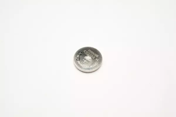
Check the voltage of the battery that was inside of your Wii. As long as it's right near 3V you can use it. If not find any coin cell that's 3V and use that in its place.
- Scratch both sides of the cell using a razor blade or craft knife.
- Tin both sides where you scratched as the solder will have an easier time sticking in these areas.
- Solder the wire we attached earlier to the underside of the MX chip to the positive side of the battery.
- Grab another strand of magnet wire and solder it to the negative terminal, and solder it onto the MX section as shown in the provided image.
(Optional) Relocating the MX Chip (3/3) - Validation
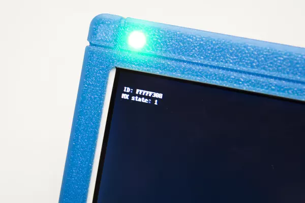
Boot into the included "CheckMX" homebrew app. If the MX state reads
1, then congratulations, your MX relocation is successful!
(Optional) Relocating Bluetooth (1/3) - Mounting
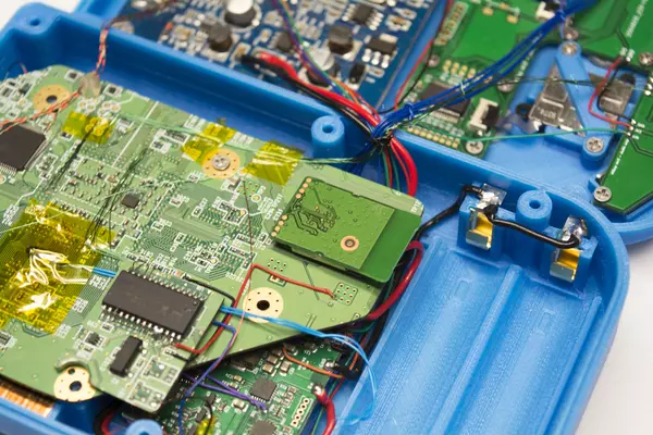
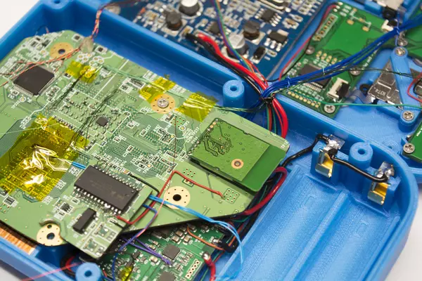
- Using a drop of hot glue on the Wii's NAND, mount the Bluetooth module as shown.
- Tin the pads shown in the image.
(Optional) Relocating Bluetooth (2/3) - Wiring
The Wii's Bluetooth module needs power (3.3V), GND, and 2 data lines to function correctly after being relocated.
- 3.3V and GND can be soldered to the points shown on the Wii motherboard (red wire - 3.3V black wire - GND)
- 3.3V must be connected between 3 different points on the module as shown.
- The two data lines are on the front of the Wii motherboard and are extremely small.
- You must scratch the solder mask off of the PCB to expose bare copper underneath in order to solder to the required points as shown in the image. To do this, we recommend using a craft knife or razor blade along with a magnifying glass or microscope if you have access to them.
- TIP: If you're having trouble soldering the two wires next to each other, you can scratch at a different point for each!
(Optional) Relocating Bluetooth (3/3) - Validation
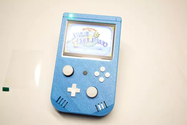
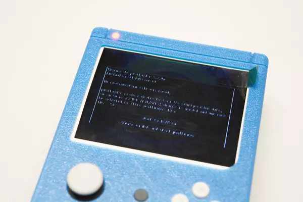
To test the relocation, all we have to do is try to boot into the Wii home menu. If you get a black screen then unfortunately your relocation was not successful. However if you get the screen pictured then you're all set and the relocation worked!
