
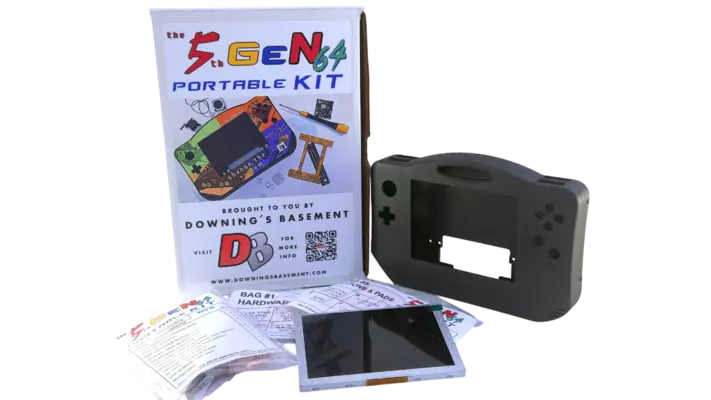
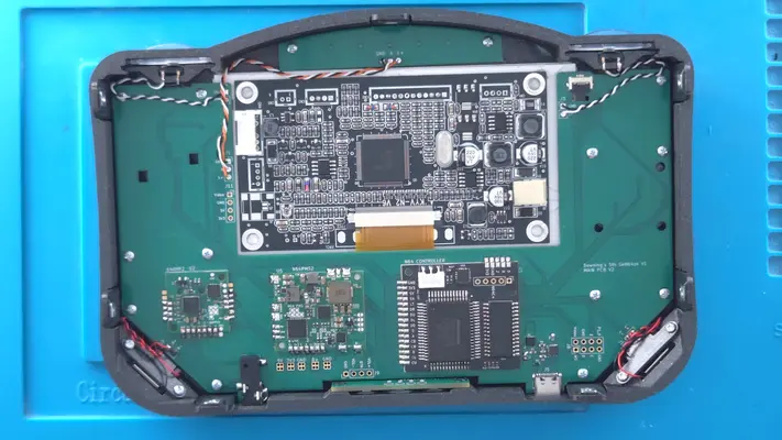
Downing's 5th GeN64 Portable Kit
Hey Everyone how's it going! This is Downing and I wanted to be the first one to welcome you to the home of "The 5thGeN64 Portable Kit" GUIDE, that will show you step-by-step how to assemble your own Portable Nintendo 64!
Thanks Everyone and Hope You Enjoy!
Introduction
Hey there! This is Downing and let me be the first to welcome you to the guide of my first successful Nintendo 64 Portable Kit! This has been a passion project of mine for over a year but a concept that I've been wanting to see since I started in this hobby almost 16 years ago.

So whereas I can show you the steps and where to place things, I can't stop you from accidently wiring the red wire to the black wire pad, or accidently ripping through the cartridge slot flex cable, or spilling your beer all over the Power Management board.
(Don't ask me how I know)
There are risks that you have to assume while taking on a project like this that I won't be able to help you with. Unintentional Damage being one of them.
Now in the instances where one of the modules are DOA, or I miscounted/omitted an item from the component bags, then yes, I'd be more than willing to help out there.
But understand that you can still mess this up in a way that could brick any number of components. And though the chances will be small if you pay attention to the guide and the warnings, they are still present and will be on you to make sure they are avoided!

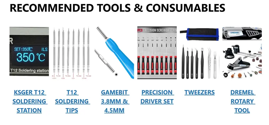
Non-Included Parts & Tools Required
In addition to what comes included with the kit, you will need some basic tools and a couple actual components that could not be included.

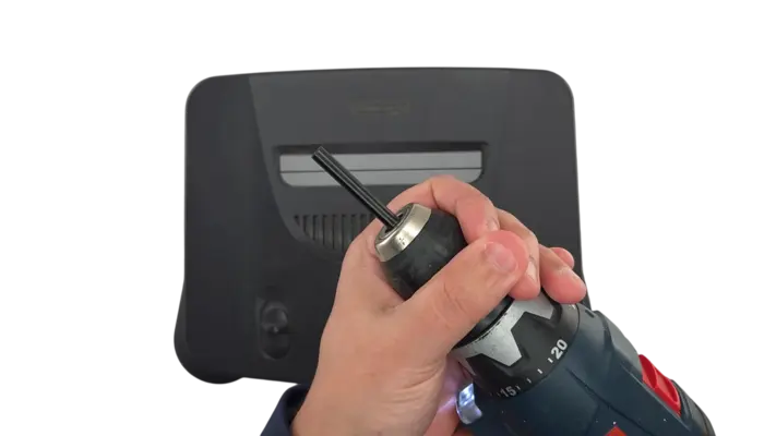
PRE-TESTING ***IMPORTANT***
Make sure your N64 is working properly BEFORE trimming the board down!!

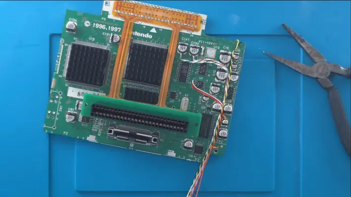
Extracting The N64 Mother Board
Kit Contents
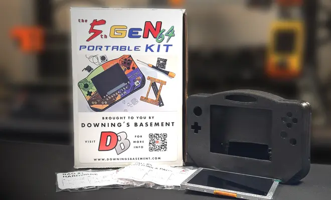
OK, once we know we have a working N64 and the kit in hand, the first step is to open the box and to verify all the contents are in there.
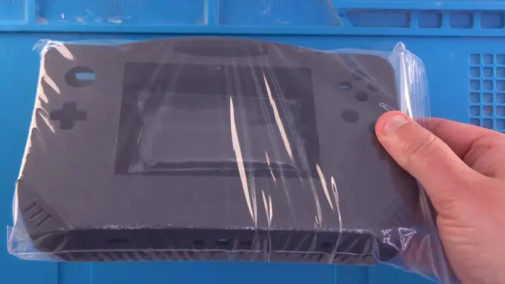
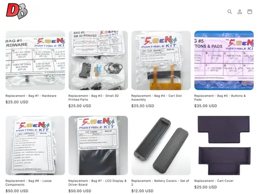
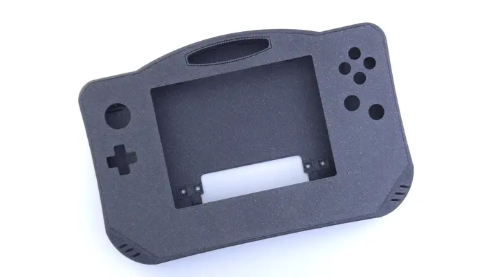
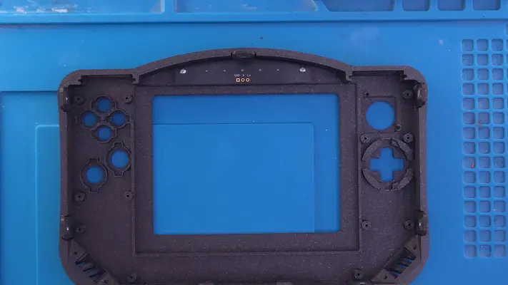
- The 3D Printed enclosure will be the first thing you see, with the battery covers taped to the inside. The cart cover will be loose underneath the insert.
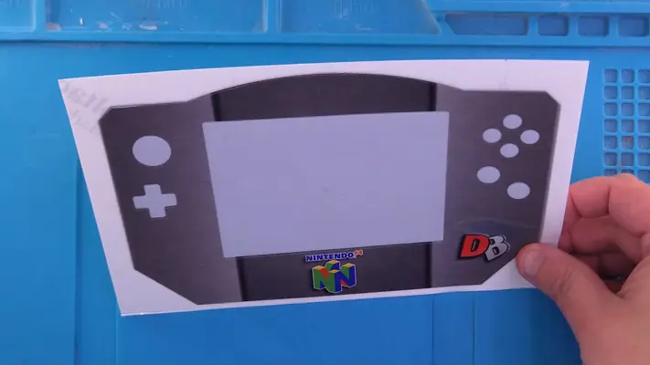
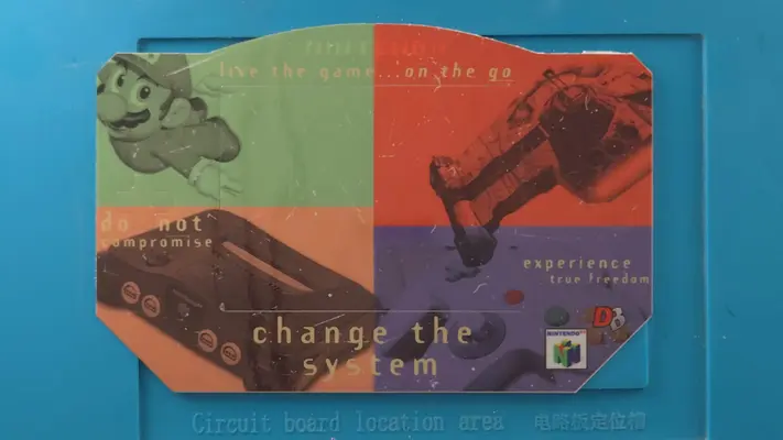
- The Laminated Vinyl Decal
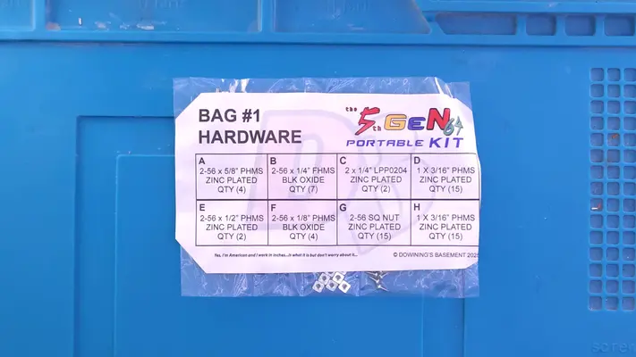
- Bag# 1 - Hardware - This bag contains all the fasteners you'll need to assemble the project. Be careful opening the pockets though as they have a tendency to fly out!
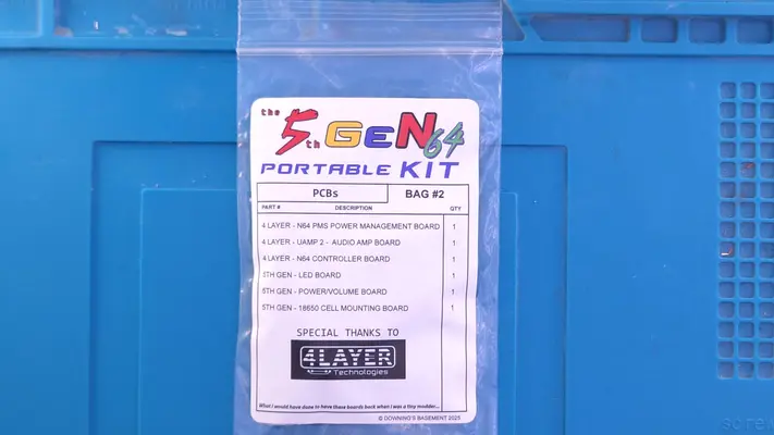
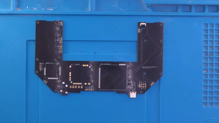
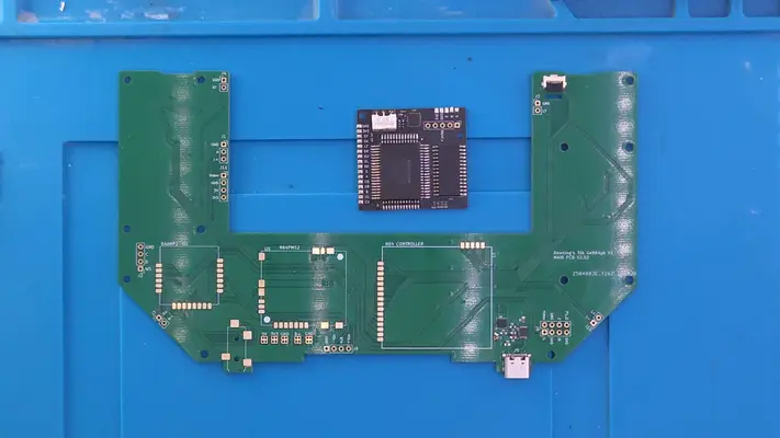
- Bag# 2 - The PCB's - This bag contains all the custom PCB's for the project, save for the main mother board that is in the main bag that holds all the other bags.
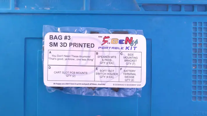
- Bag# 3 - SM 3D Printed Parts - This bag contains all the small 3D parts for the project. Note that the 2 Alignment parts are no longer needed and have been crossed off.
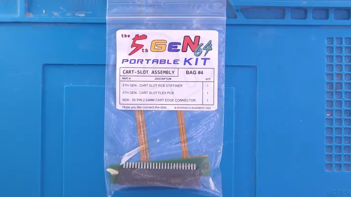
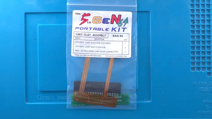
- Bag# 4 - The Cart Slot Assembly - This bag contains the three components needed for the cart slot relocation.
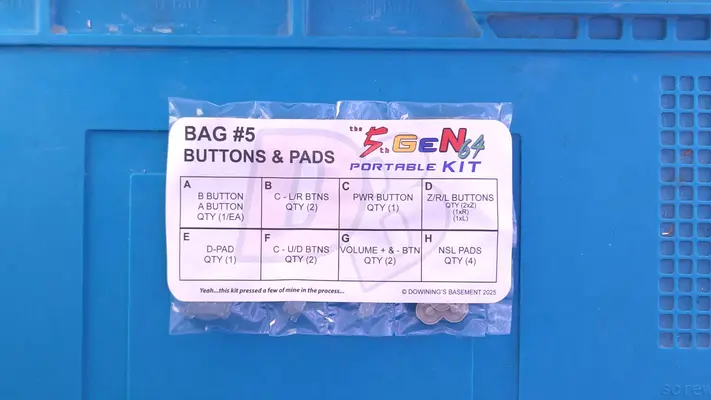
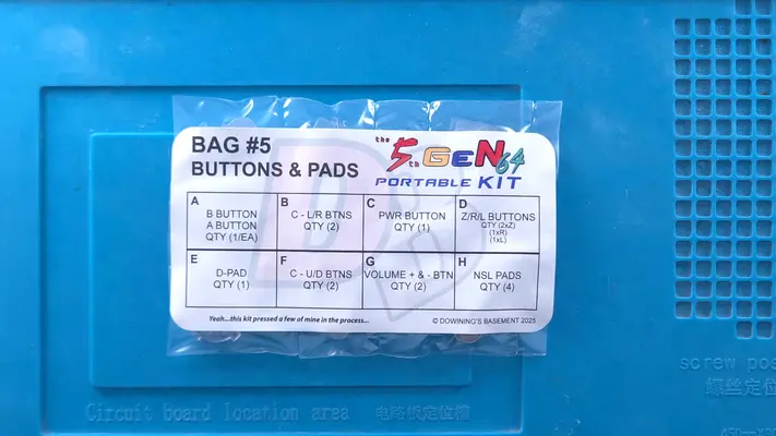
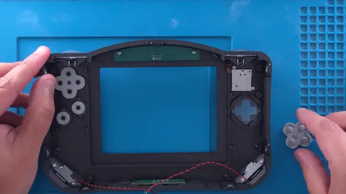
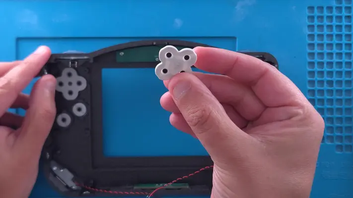
- Bag# 5 - Buttons & Pads - This bag contains all the buttons needed for the controller buttons.
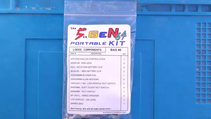
- Bag# 6 - Loose Components - This bag has everything from the Joy Con and heat sinks, to the LED acrylic backer.
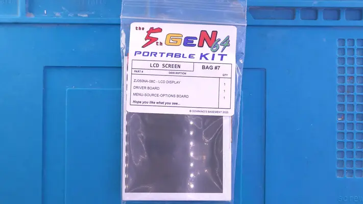
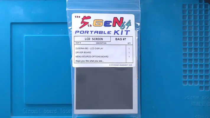
- Bag# 7 - Screen & Driver Board - Self Explanatory
Please note that the PCBs may be different colors than the one's shown in the guide as the images were being captured using the prototype versions. Functionally they are the same unless otherwise noted.
5TH GeN64 Store Now Open!
That's right, for the first time ever I now have an actual online storefront for all things 5th Gen64 Kit related! That means if you need spare parts or what to buy a full blown kit, you now have a place to do so!
UPDATES
As the kits progress and new techniques, issues or methods are discovered, they will be listed here and linked to their respective detailed steps or just explained in a dedicated step below.
Please check back to this step frequently if you're in the process of a build as it will have the potential to make a difference in how you're putting the unit together!
ISSUES
RESOLUTION - STEP UPDATED HERE 2-27-26
RESOLUTION - STEP UPDATED HERE 2-27-26
RESOLUTION - SCREEN INSTALLATION STEP BEING UPDATED

PART I - COMPONENT REMOVAL
SECTION SUMMARY
Component Removal is our first step in preparing the N64 Motherboard for trimming.
These Steps Will Require:
- Removing The Stock Heat Sinks
- Removing The Original Cartridge Slot
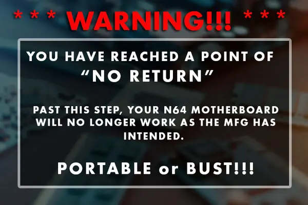
- Hitting A No Return Point
- Removing The DD Slot
- Stock Component Removal In Prep for Trimming
OVERALL DIFFICULTY - EASY
CRITICAL STEP AND/OR SAFETY NOTICE
CRITICAL STEP AND/OR SAFETY NOTICE
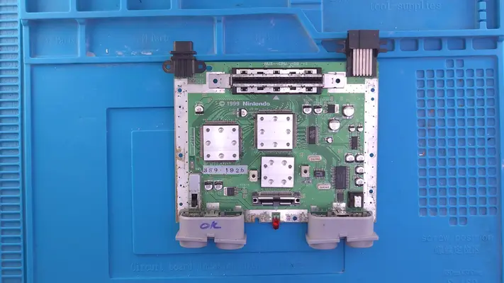
Remove The Stock Heatsinks
STEP SUMMARY We will be removing the stock heatsinks that came with the N64 and replacing them with lower profile, more efficient Aluminum RAM heatsinks.
DIFFICULTY - EASY
TOOLS NEEDED
- NONE
MATERIALS NEEDED
- NONE
PARTS NEEDED
- N64 Motherboard
STEP PROCESS
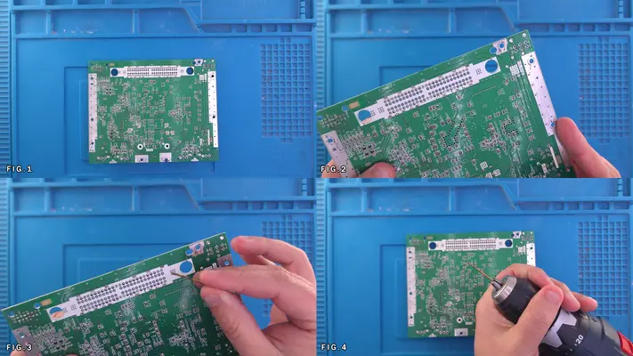
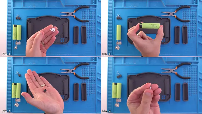
1. The three heatsinks come off with minimal effort as a simple twisting motion will remove them. Make sure the thermal pad comes off with the heat sink as we will not be needing them. 2. Discard or recycle these as we will not be needing them again.
3. Proceed to "CART SLOT REMOVAL"
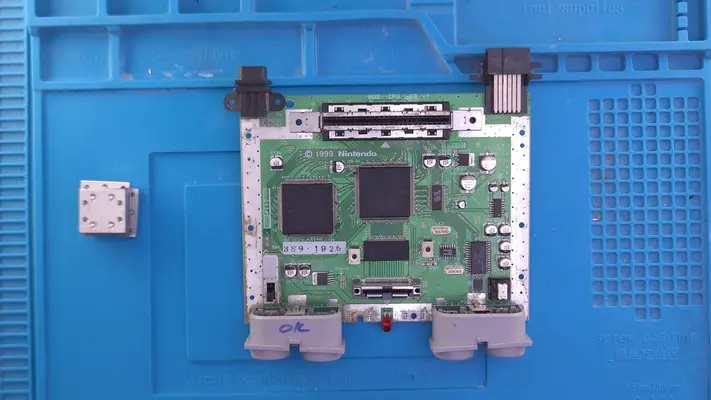
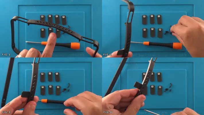
Cart Slot Removal
STEP SUMMARY Like the heatsinks, the Original Cart Slot needs to be removed as we will upgrading to a more modern (and clean) card-edge connector later on.
DIFFICULTY - EASY
TOOLS NEEDED
- NONE
MATERIALS NEEDED
- NONE
PARTS NEEDED
- N64 MOTHERBOARD
STEP PROCESS
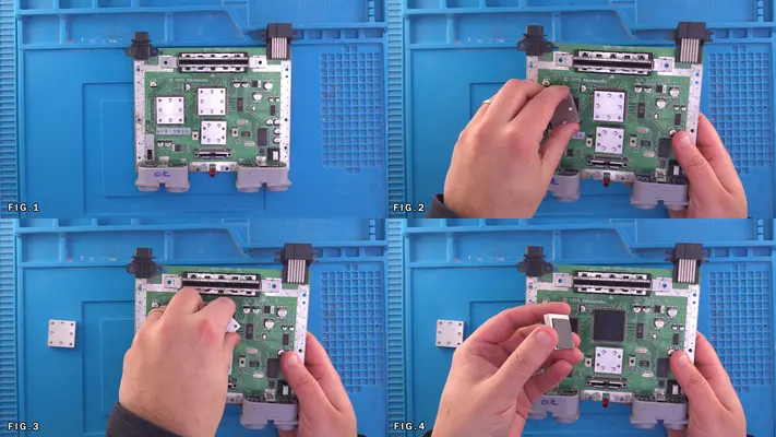
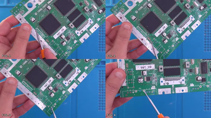
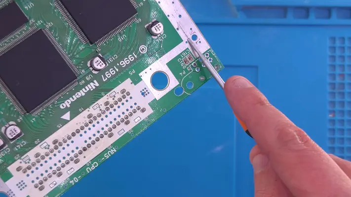
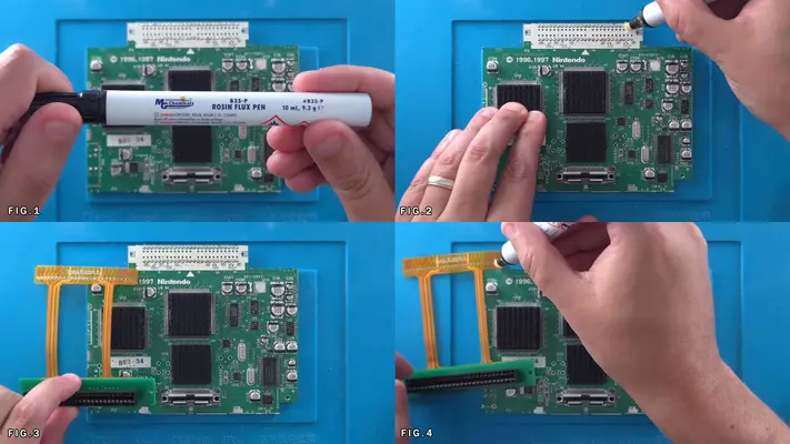
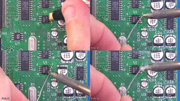
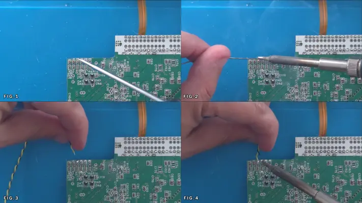
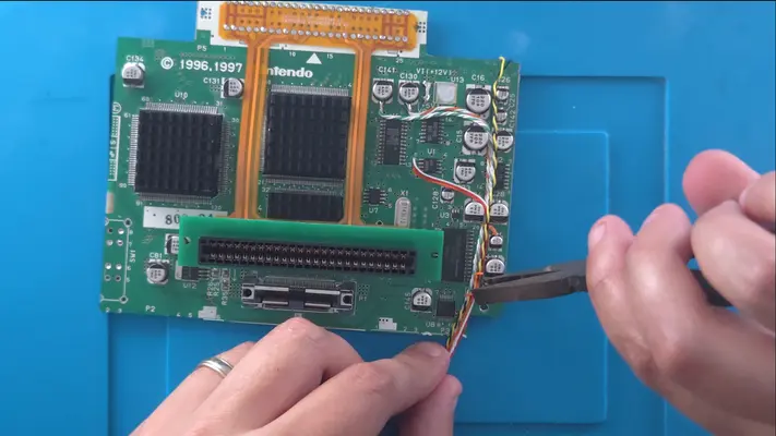
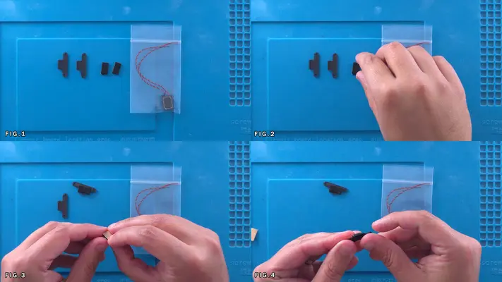
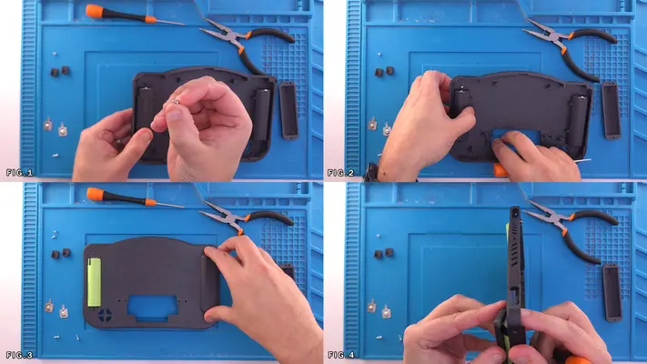
1. The cart slot is only held in by pressure and can be easily pulled from its seat.
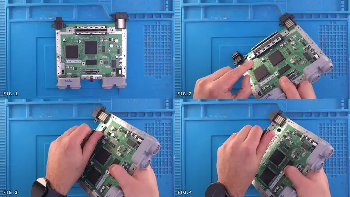
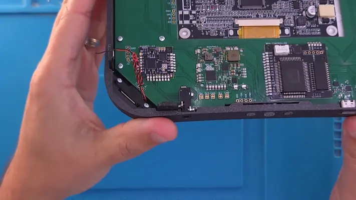
2. Grab the whole front & back as shown in Fig.3 and gently rock the cart slot front to back while pulling straight up.
3. The cart slot should pull right out and we can now set it aside or discard as we will not be using it going forward.
Proceed to next step.
Point of NO RETURN
Up to this point, by simply placing the cart slot and jumper pak back, you could put the motherboard back in the original enclosure and be on your way.
Removing The DD Slot
STEP SUMMARY
The DD Slot was an expansion dock that was never used in the USA, nor will it be used in this portable, so we need to remove it. It is a bit more of an involved process to remove cleanly and though the video is older, the process hasn't changed.
DIFFICULTY - MODERATE
TOOLS NEEDED
- PRECISION FLAT HEAD SCREW DRIVER
- SOLDERING IRON - SOLDER BRAID OR DESOLDERING PUMP
MATERIALS NEEDED
- SOLDER
- FLUX
PARTS NEEDED
- N64 MOTHERBOARD
STEP PROCESS
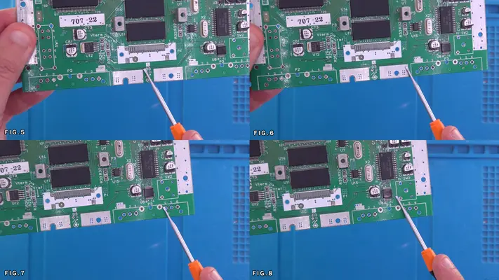
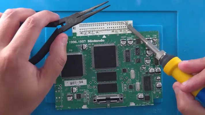
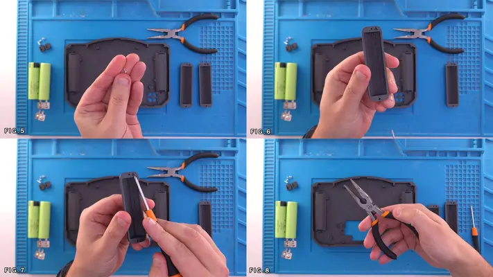
This part is a little more involved as it will require prying off the back shielding, pulling the connector off the pins, and then breaking or de-soldering the pins.
Removal of Connectors, Switches, Brackets and LED
STEP SUMMARY
Once the DD slot has been removed, there are a few components we will still need to remove before we can begin to trim the board. Again, the videos below are older, but the methods remain the same. Just be aware that the controller ports and the power switch are particularly difficult to loosen up and will need to be worked.
DIFFICULTY - MODERATE
TOOLS NEEDED
- SOLDERING IRON
- DESOLDING BRAID OR PUMP - HEAVY DUTY PLIERS - PRECISION FLAT HEAD SCREW DRIVER
MATERIALS NEEDED
- SOLDER
- FLUX
- ISOPROPAL ALCOHOL - Q-TIPS OR COTTON SWABS
PARTS NEEDED
- N64 MOTHERBOARD
STEP PROCESS
These parts being:
- The Controller Ports
- The Main Power Switch
- The Reset Button
These two videos are also pretty old but they do a good job of demonstrating the removal of all non-required components.
None of these components that are being removed will be used again, so if you damage them taking them off, don't worry about it.
PART II - DRILLING & TRIMMING THE N64 MOBO
OVERALL DIFFICULTY - MODERATE
CRITICAL STEP AND/OR SAFETY NOTICE
RISK OF N64 MOTHERBOARD DAMAGE WHILE TRIMMING
SAFETY GLASSES AND DUST MASK ARE HIGHLY RECOMMENDED FOR THESE STEPS!
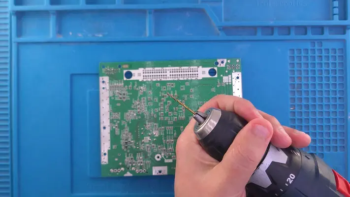
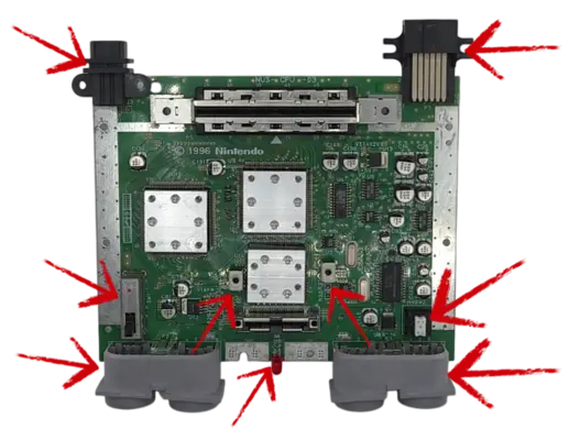
Drilling The N64 Mobo Mounting Holes
STEP SUMMARY
This step we will be drilling a mounting hole as well as cleaning up a couple mounting points that are already on the board.
DIFFICULTY - EASY
TOOLS NEEDED
- CORDLESS DRILL
- 1/16" or 2mm DRILL BIT
MATERIALS NEEDED
- None
PARTS NEEDED
- N64 MOTHERBOARD
STEP PROCESS
2. You will notice that the case has two standoffs for this purpose, but we will only be using one, as I discovered later, drilling a hole in that spot caused a problem.
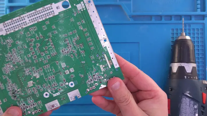
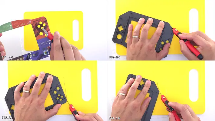
The Cut Path - CUTTING - Manual Trim w/Rotary Tool
STEP SUMMARY
Unlike other more complex board trims, this one is as straight forward as I could possibly make it. While I fortunately have the ability to cut mine on a CNC machine, it can be done well enough by hand with a rotary tool and a bit of patience. The key is not to rush and to keep a steady hand and stay on the "waste side" of the line.
SAFETY GLASSES RECOMMENDED FOR THIS STEP!
DIFFICULTY - MODERATE
TOOLS NEEDED
- ROTARY TOOL W/STANDARD OR DIAMOND CUT WHEEL
- RULER AND MARKER (OPTIONAL)
MATERIALS NEEDED
- 220 GRIT SAND PAPER OR NAIL FILE
PARTS NEEDED
- N64 MOTHERBOARD
STEP PROCESS
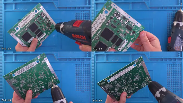
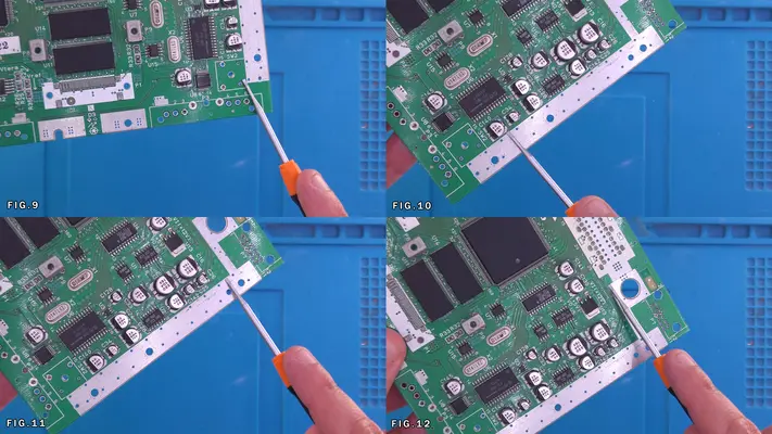
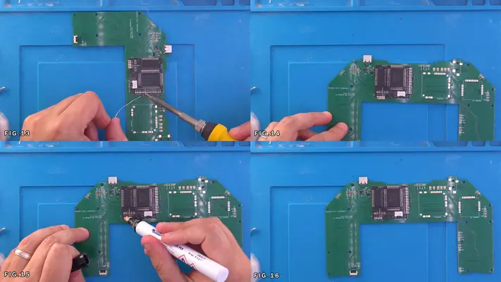
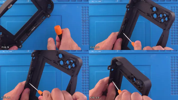
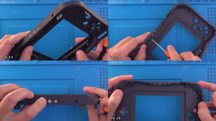
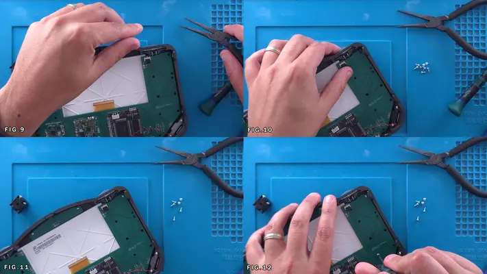
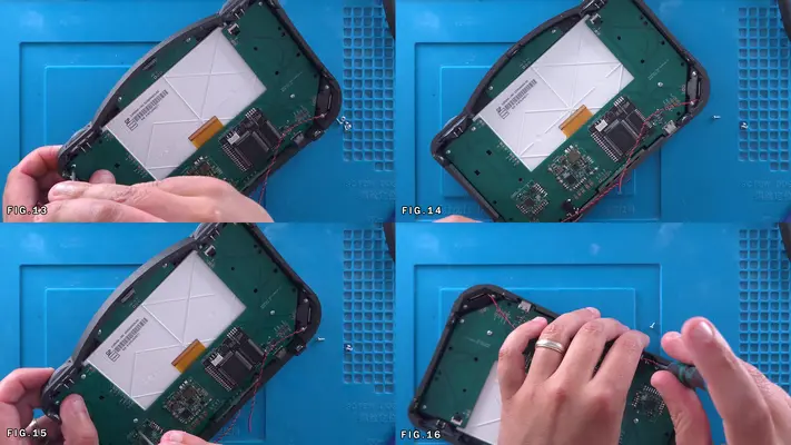
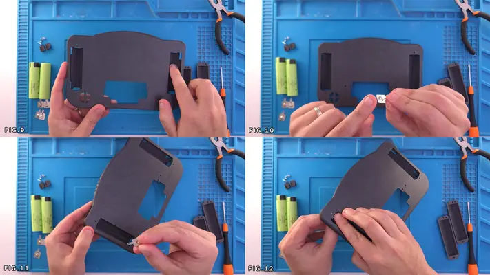
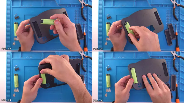
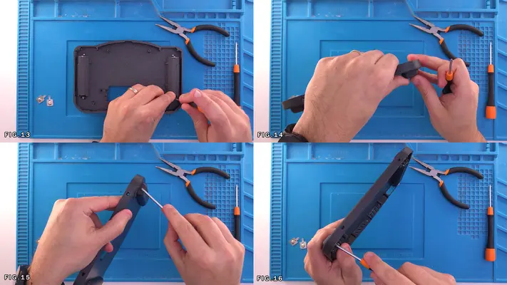
9. The vertical cut then needs to go up to split the shielding mounts of the DD slot right in half. Fig.14-16
PROCEED TO PART III
PART III - PREPARING THE TRIMMED N64 MOTHERBOARD
- Preparing the Solder Points for the Cart Slot Cable
- Installing Upgraded Heatsinks
- Removal of stock 7805 Power Regulator
- Assembling the Cart Slot
- Soldering the Cart Slot to The Trimmed N64
- Wiring the 3.3V and 5V Power Lines
- Wiring the Video Output Line
- Wiring the Audio Output Lines
- Wiring the Controller Data Output Lines
- Wiring the Reset Cables
OVERALL DIFFICULTY - MODERATE
CRITICAL STEP AND/OR SAFETY NOTICE
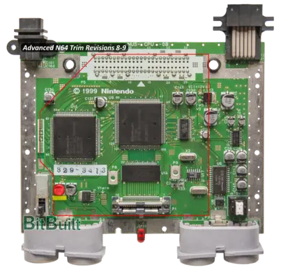
UPDATE for I1 - C81 Removal For Rev 8-9 Board Versions
As was found out a couple weeks ago, N64 Motherboards Revision 8-9 (1999 or above) had a different placement for Cap C81, which subsequently came into contact with the blower fan and did not allow the N64 motherboard to be mounted properly.
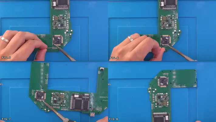
Preparing The Solder Points for The Cart Slot Cable
STEP SUMMARY
This step's difficulty is largely going to depend on if you took the easy "break the pins" method from the DD Slot Removal step, or if you took you time and removed each pin. Personally I've found it more difficult to pull the pins first rather than break them, but then we end up in this situation, which is the one most of you will probably be in, so here we go.
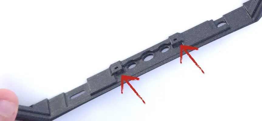
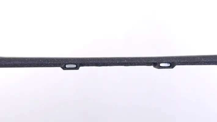
It's critical that the flex cable has a solid and obstruction free place to mount too, and to do so, we have to remove all leftover pins from the DD slot and the shielding that held it in place (the little oval slots).
DIFFICULTY - MODERATE
TOOLS NEEDED
- SOLDERING IRON
- NEEDLENOSE PLIERS AND/OR TWEEZERS
MATERIALS NEEDED
- SOLDER
- DESOLDERING BRAID OR PUMP
- FLUX - ISOPROPAL ALCOHOL
- Q-TIP OR COTTON SWABS
PARTS NEEDED
- N64 MOTHERBOARD
STEP PROCESS
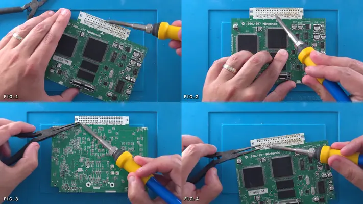
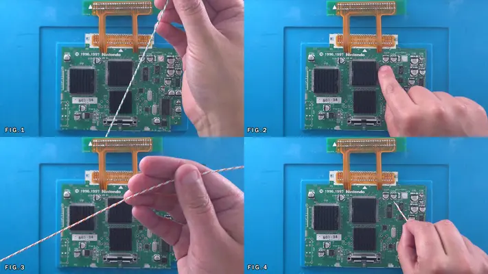
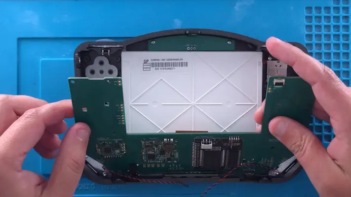
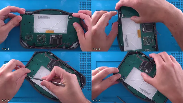
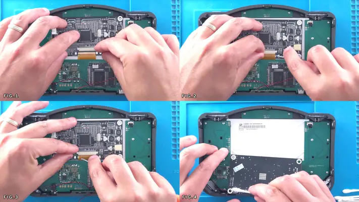
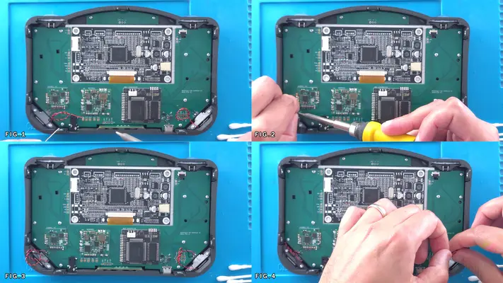
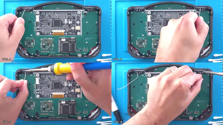
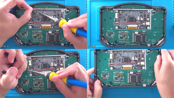
1. Removing the remaining pieces of pins is a tedious process to say the least but is the only way to ensure a solid connection with the cart slot flex cable.
2. Heating up each pin from the front of the board and pushing the pin flush with the pad will make removal from the back side of the board much easier.
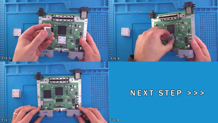
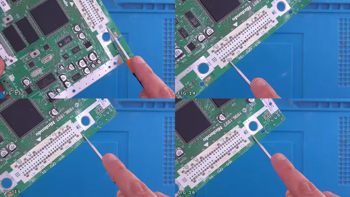
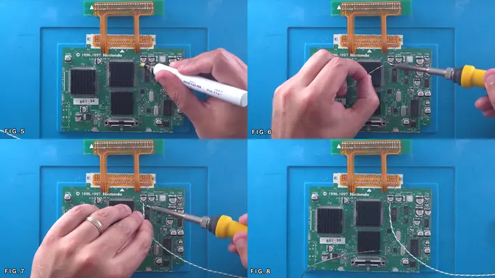
3. Once all 50 pins have been hit, flip the board over as seen in Fig. 3 and heat the pads while holding onto the pin with pliers and then remove. This may not be as simple of a process as it seems.
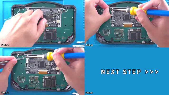
4. After all the pins have been pulled, clean the pins with ISO on both sides of the board.
5. Hit all the pins with FLUX and fill in with solder so there is a nice shiny dome on each pin and then clean all the remain FLUX off with some more ISO.
PROCEED TO NEXT STEP

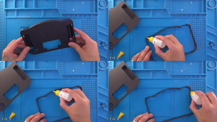
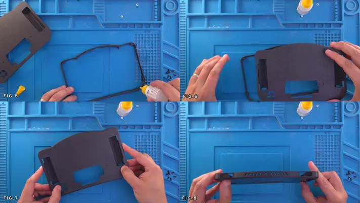
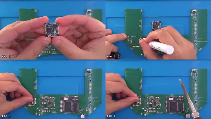
Installing Upgraded Heat Sinks
STEP SUMMARY
We needed to remove the stock heatsinks because they were basically just solid blocks of Aluminum that were held in place by an even bigger heat sink plate. These newer, low-profile, self-adhesive heatsinks do a much better job dissipating heat, though I find their adhesion to be a bit sub-par, so we'll have to tack them in place with something a bit stronger.
DIFFICULTY - EASY
TOOLS NEEDED
- NONE
MATERIALS NEEDED
- GOOP
- Q-TIP
PARTS NEEDED
- QTY (3) - BAG# 6 - ALUMINUM HEAT SINKS
STEP PROCESS
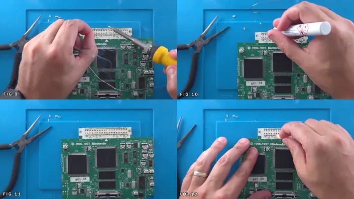
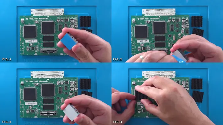
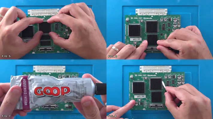
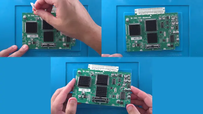
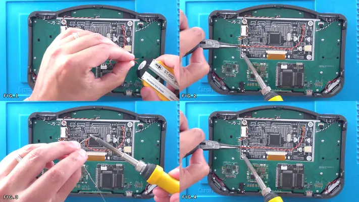
1. Remove the 3 heat sinks from the bag and peel off the backer.
2. Carefully place one heatsink on the CPU, the RCP and RAM chips as shown in Fig. 1-6
Though these are self adhesive, I prefer to add a bit of insurance to process.
3. With a small dab of "Goop", put a small bit on either side of all the chips/heatsinks. This will make sure they don't come off unless intended.
NOTE: Later versions of the N64 only have a single RAM chip, in which case, find the 1" long piece of black foam tape in the "SPARES BAG" to fill in the gap.
PROCEED TO NEXT STEP

Removing The 7805 5V Regulator
STEP SUMMARY
Because we will be using our own Power Management Solution later down the road, we need to remove the onboard 7805 Regulator so we don't double regulate our 5v power rail.
DIFFICULTY - EASY
TOOLS NEEDED
- FLUSH CUTTERS OR DIAGONAL PLIERS
- SOLDERING IRON - NEEDLENOSE OR FLATNOSE PLIERS
MATERIALS NEEDED
- FLUX
PARTS NEEDED
- N64 MOTHERBOARD
STEP PROCESS
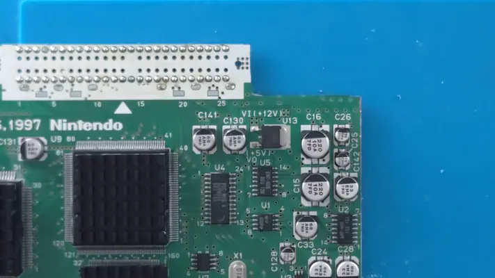
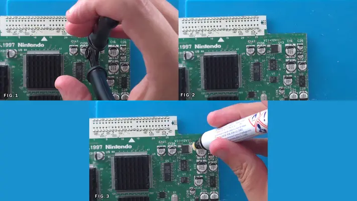
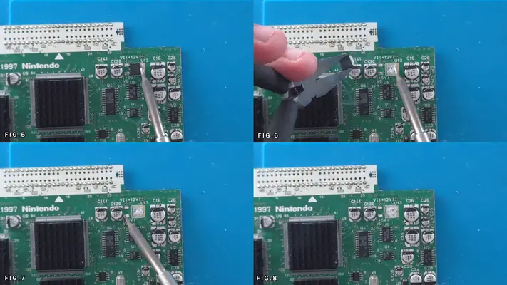
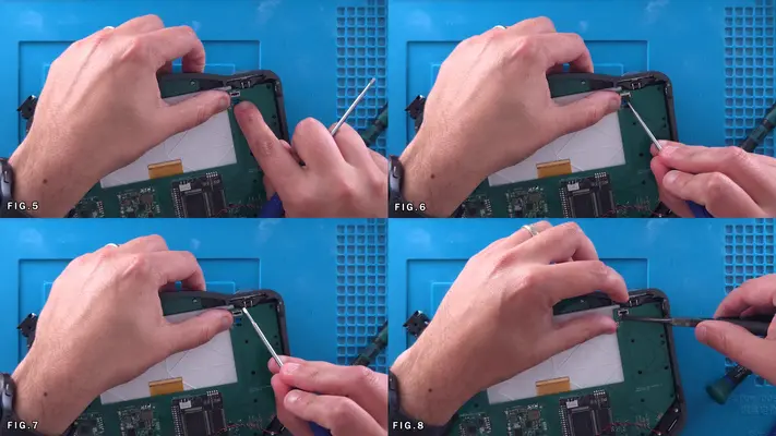
1. Start by clipping the two small legs of the 7805, preferably with Flush Cutters as shown in Fig.1
2. Hit the whole back side of the regulator with some Flux.
3. With the soldering iron, begin to heat the regulator and the pad, keeping in mind that depending on what kind of tip you are using on your iron, may take a bit of time to heat up.
4. When the regulator starts to loosen up, take your pliers and completely remove the reg.
5. Clean up where you cut the legs and make sure what's left over has been removed and the pads are clean. PROCEED TO NEXT STEP
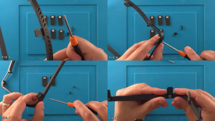
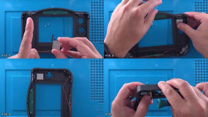
Assembling The Cart Slot
STEP SUMMARY
Perhaps one of the biggest time savers to every come to portablizing, custom Flat Flexible Cables were a game changer when they came out. This mini assembly is a quick and easy alternative to cutting, stripping and wiring up 50 wires.
DIFFICULTY - EASY
TOOLS NEEDED
- SOLDERING IRON
MATERIALS NEEDED
- SOLDER
PARTS NEEDED
- QTY (1) - BAG# 4 - 50 PIN CART EDGE CONNECTOR
- QTY (1) - BAG# 4 - CART SLOT STIFFENER PCB
- QTY (1) - BAG# 4 - CART SLOT FLEX PCB
STEP PROCESS
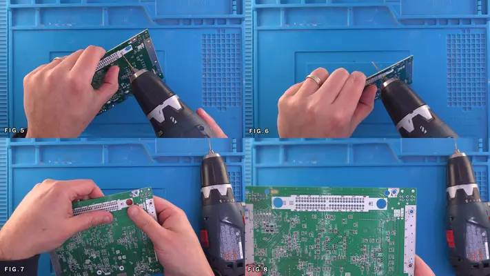
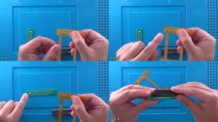
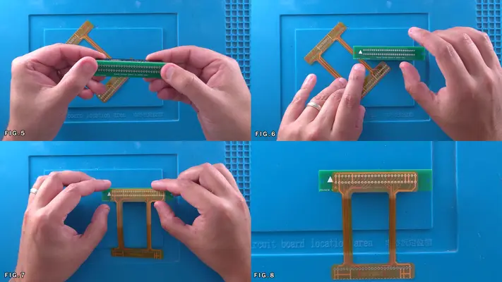
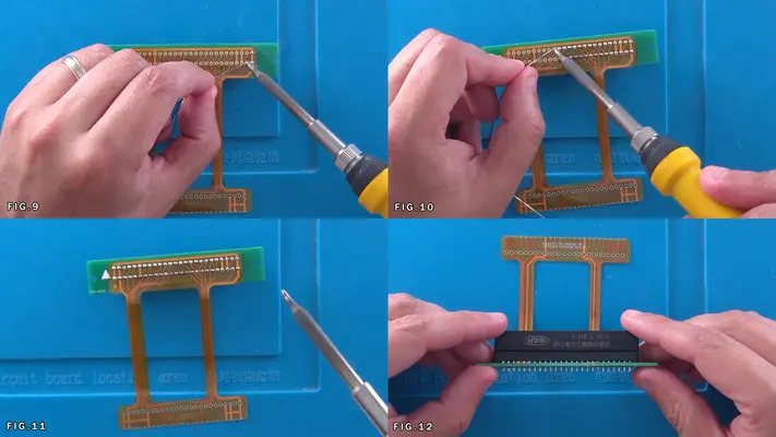
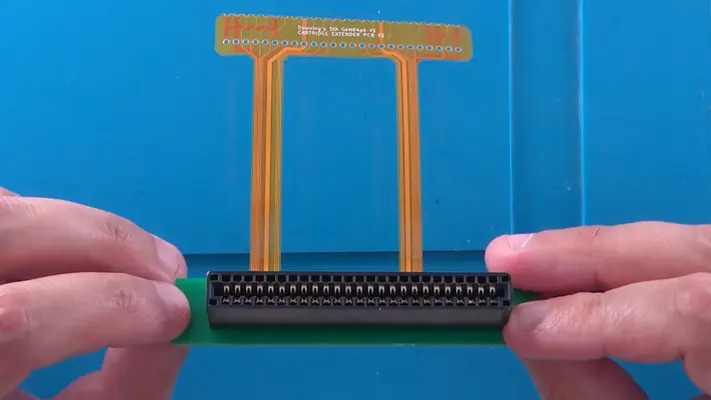
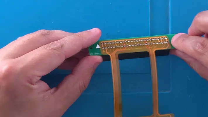
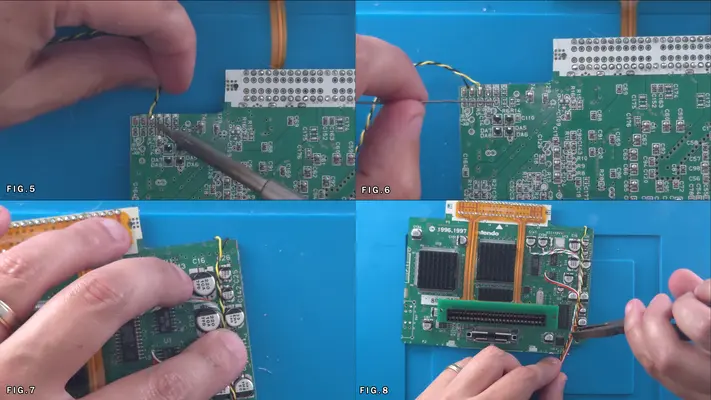
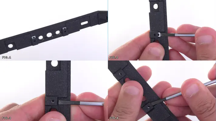
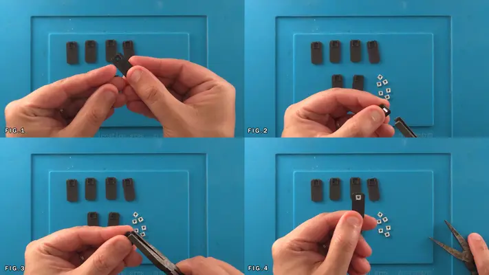
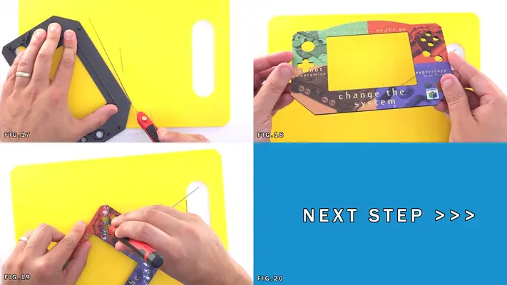
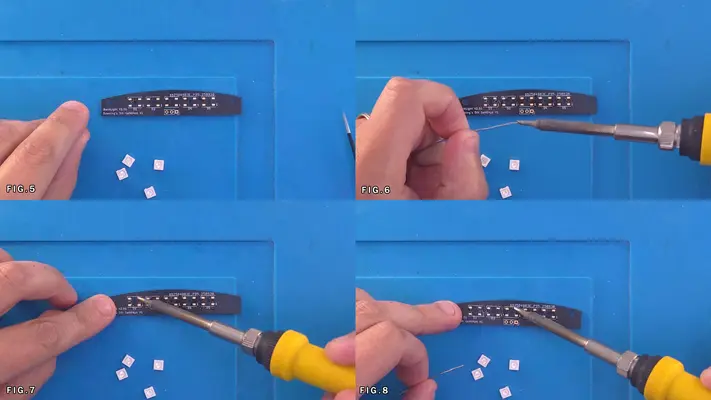
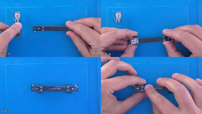
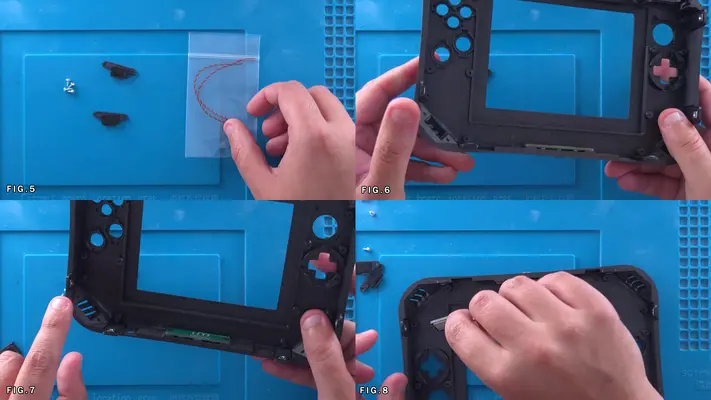
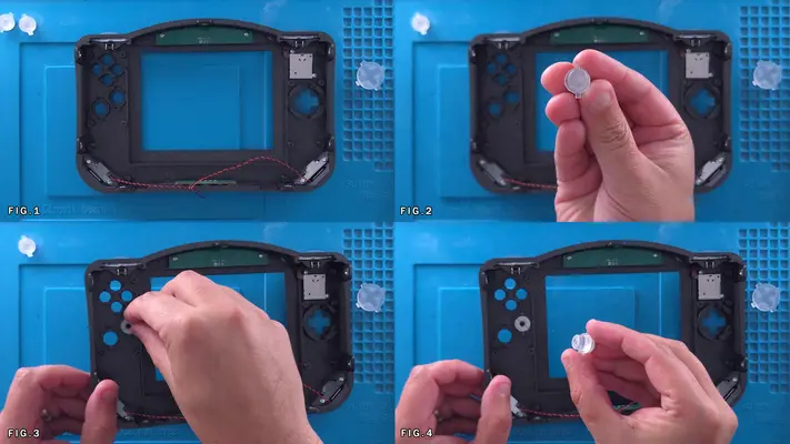
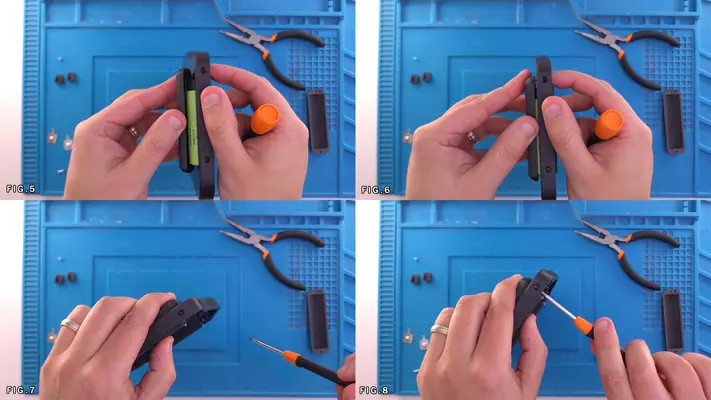
1. Remove the Flex PCB and the Stiffener from the bag and look for the printed triangles on both as seen in Fig. 2&3
2. Flip over the Stiffener PCB so the arrow is face down pointing toward you and take the Cart Edge Connector and place it through the holes on the PCB with the text on the Connector facing you as seen in Fig. 4
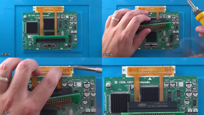
3. Flip both over again so the arrow on the PCB is both facing and pointing up as shown in Fig. 6
4. Find the arrow on the Flex Cable and match the side and direction with the arrow on the PCB. NOTE: There are multiple versions of the Stiffener and some may just have a decal on them while later versions, the two arrows will overlay one another. This makes no difference in functionality.
5. Lay the Flex Cable over the Stiffener so the Cart Slot Pins are going through both of them as shown in Fig. 7&8
6. Begin to solder pin to pin, starting from on side and making your way across, being careful to make sure the Flex Cable and the Stiffener are all sitting as flat as possible on the Cart Slot.
7. Once complete, inspect all points to make sure everything is clean and soldered solid and that there are no tares in the Flex Cable. It is also highly recommended that you test each pin connection with a continuity meter just to make sure your connection is good. PROCEED TO NEXT STEP
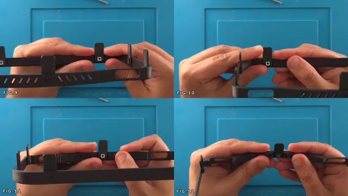
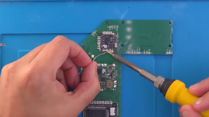
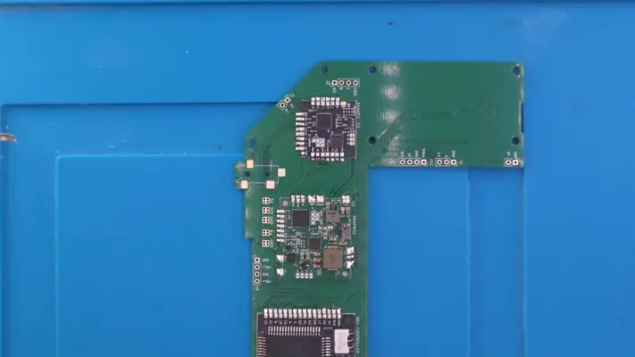
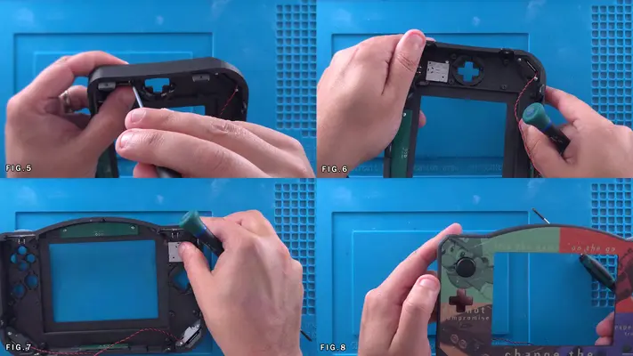
Soldering The Cart Slot to The Trimmed N64
STEP SUMMARY
Once the cart slot assembly is complete and the solder points on the N64 have been cleaned up we can now connect the two. This step is very easy, but take your time to make sure you do it correctly as having to remove the Flex cable after it's been soldered tends to end poorly.
DIFFICULTY - EASY
TOOLS NEEDED
- SOLDERING IRON
MATERIALS NEEDED
- SOLDER
- FLUX
- ISOPROPAL ALCOHOL
- Q-TIP OR COTTON SWAB
PARTS NEEDED
- ASSEMBLED CART SLOT ASSEMBLY
- TRIMMED AND DRILLED N64 MOTHERBOARD
STEP PROCESS
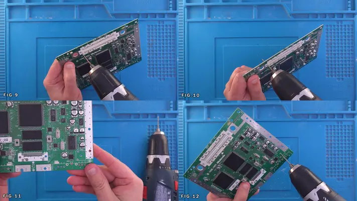
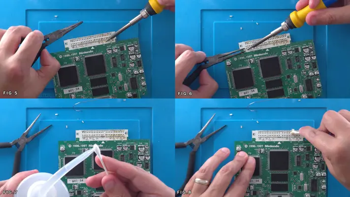
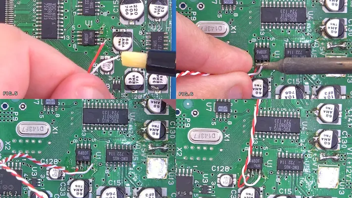
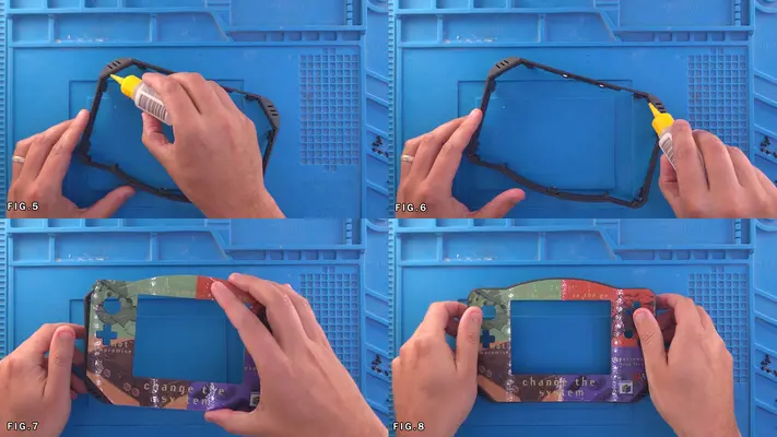
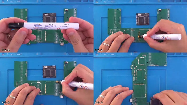
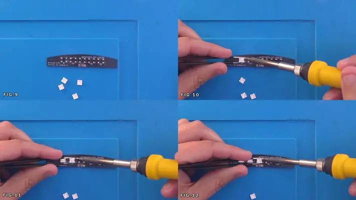
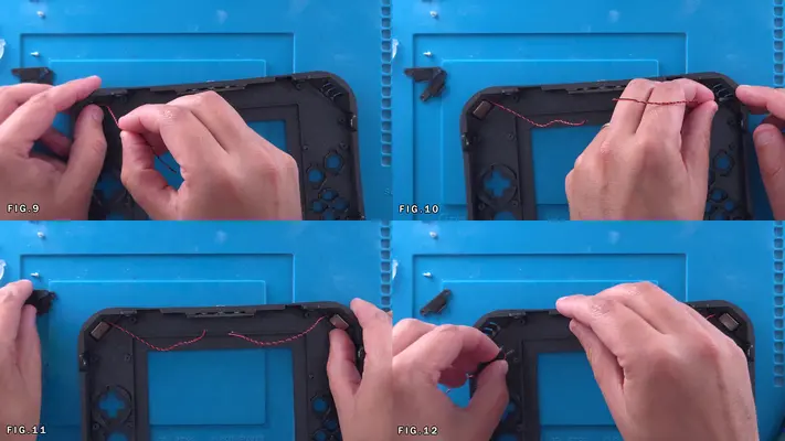
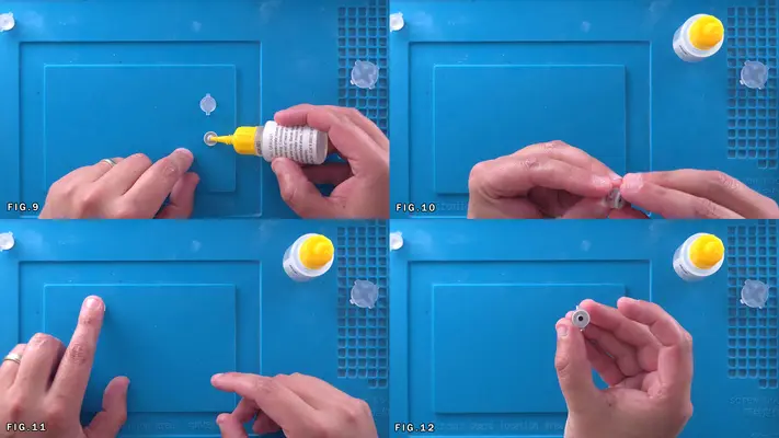
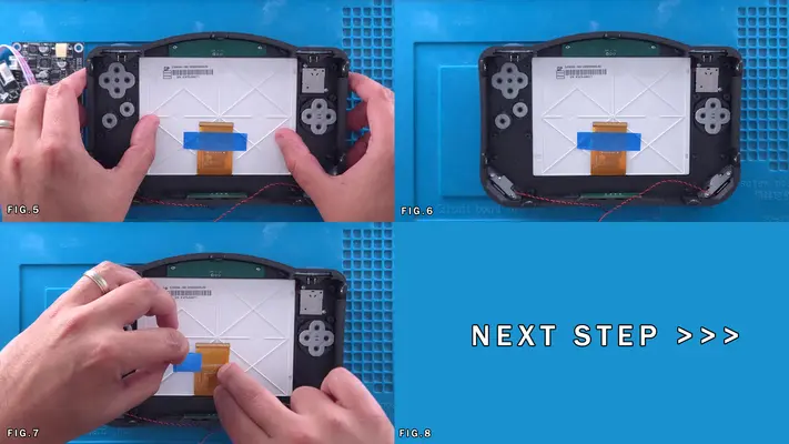
1. Apply Flux across the solder points on the N64 as shown in Fig. 1&2
2. Repeat the process for the Flex Cable as shown in Fig. 3&4
3. Making sure that the text on the Flex Cable is facing up, line up the Flex Cable with the Solder points on the N64 as shown in Fig. 5&6
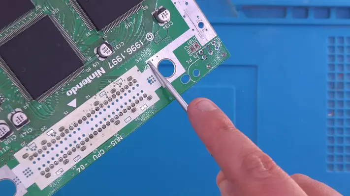
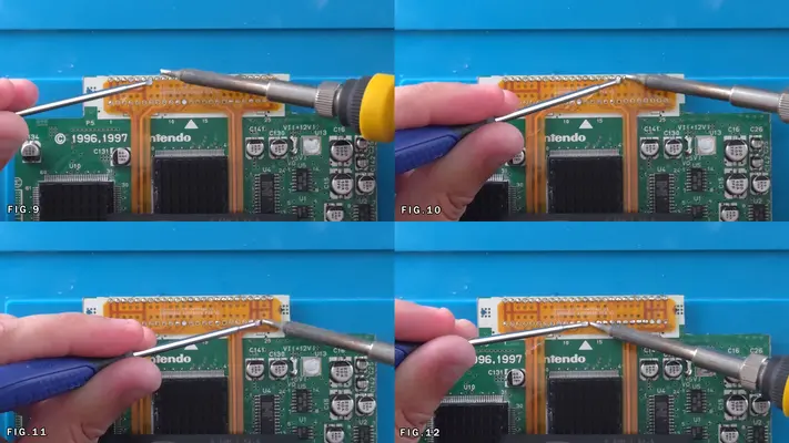
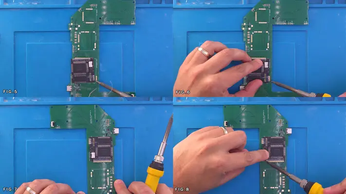
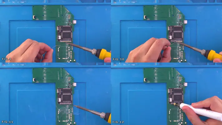
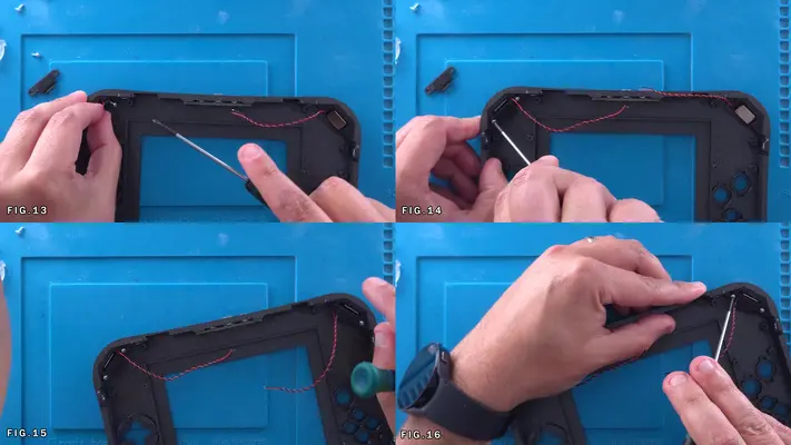
4. Like before, start on one side and start working your way to the other, one pin at a time. To make sure it stays as flat as possible I'll often use a precision flat head screwdriver to press the cable to the pad as I'm going as shown in Fig. 9-13
Now even though it may feel like it's soldered well at this point, we've only used solder from the N64 that was there from the boards preparation step earlier. To make sure it's really solid, we may need to hit it with solder from the top as well.
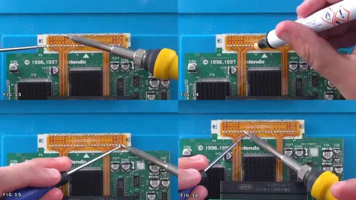
6. Take the Flux again and run across the top of the Flex Cable as shown in Fig. 14
7. Hit all the pads with your iron, adding solder to any that don't look to have the pad completely covered with solder.
8. When complete, clean up any residual Flux with the ISO and you should be left with a nice and shiny little dome of solder on each pin connection.
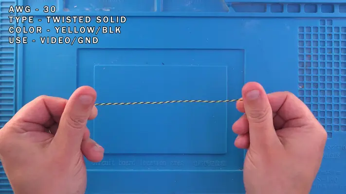
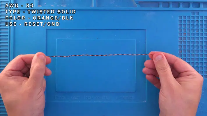
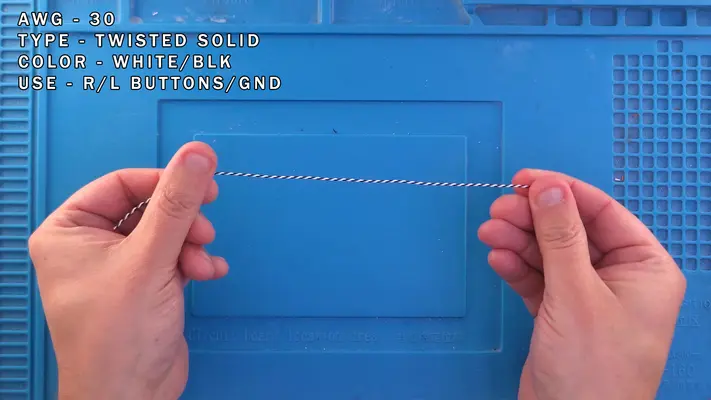
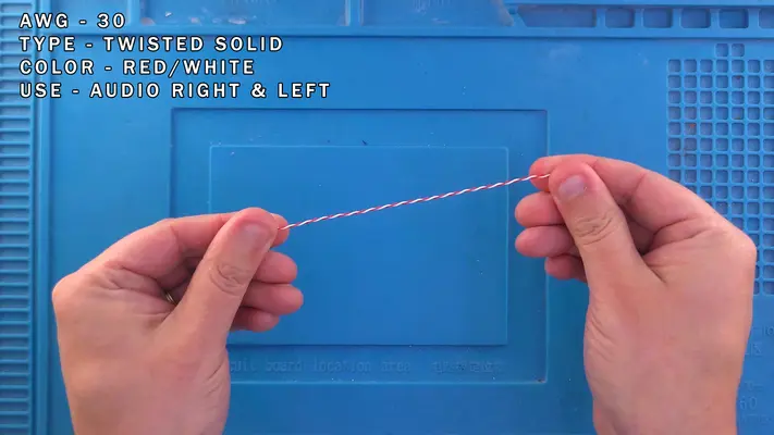
Wire Color Codes and Gauges
Now this section is not really a requirement on your end, but makes keeping track of various wires a much simpler task as the build progresses. As long as your wire gauges match the load, you really can use whatever wire and color combination you choose.
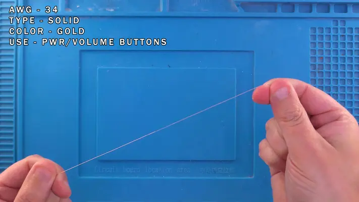
Gold - Power/Volume Button Board
30 AWG Solid
Black - GND
Green - P1_D
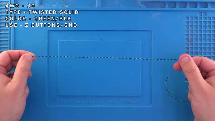
30 AWG Twisted Pair
Green/Black - Z Buttons/GND
Yellow/Black - Video/GND
Orange/Black - Reset Button/GND
White/Black - R/L Buttons/GND
Red/White - Right & Left Audio
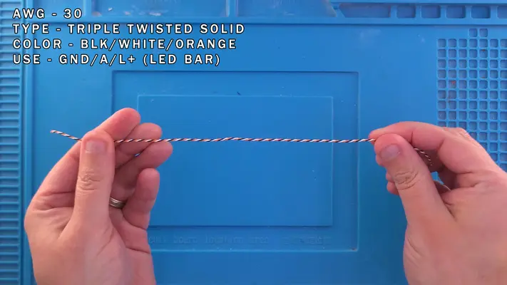
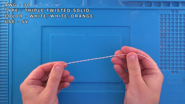
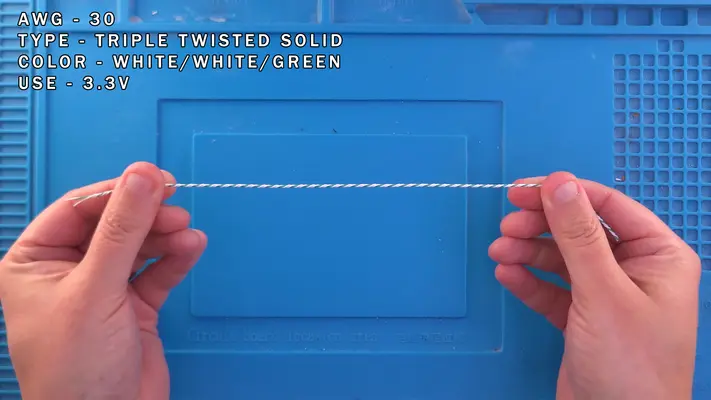
30 AWG Twisted Triple
Blk/White/Orange - GND/A/L+
Blk/Orange/Red - 5V w/GND (Screen)
White/White/Orange - 5V
White/White/Green - 3V
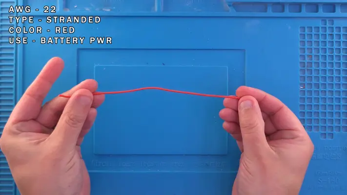
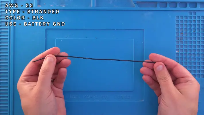
22 AWG Stranded
Red - 3.3V/Batteries
Black - GND/Batteries
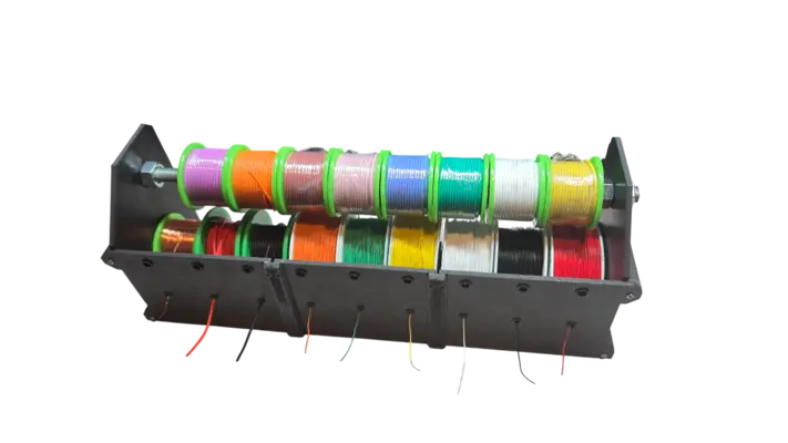

Twisting Wire
STEP SUMMARY
Again, this is an optional step, but I find that it makes keeping track of what wire is which, and also makes wire management far easier, it's highly recommended.
DIFFICULTY - EASY
TOOLS NEEDED
- CORDLESS DRILL
- FLATNOSE PLIERS
MATERIALS NEEDED
- 30AWG WIRE OF VARIOUSE COLORS
PARTS NEEDED
- NONE
STEP PROCESS
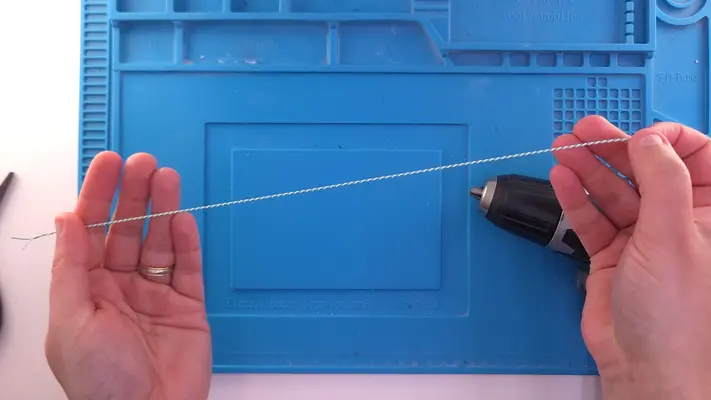
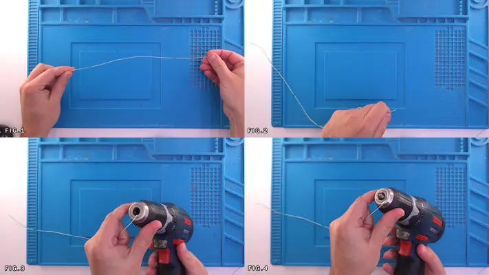
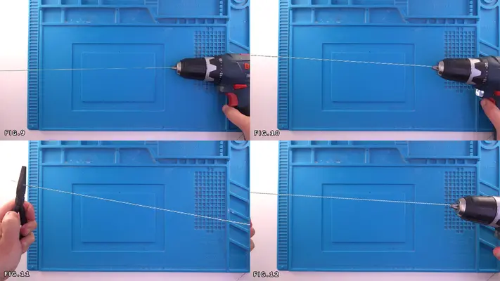
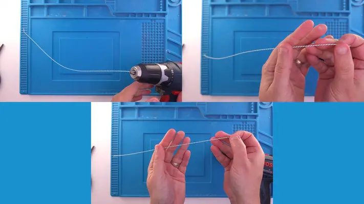
1. For a standard Twisted Pair of wire, cut two strands of wire of two different colors (Red & White as an example) about 12" long. Fig.1
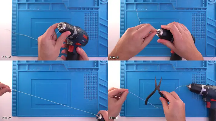
2. Feed one end of the pair into the chuck of the drill as shown in Fig.5 & 6
3. Pull the wires taught to make sure they won't pull out of the chuck. Fig.9 & 10
4. Grip the other side with the Flatnose Pliers and pull tight.
5. Squeeze the trigger of the drill and start to twist the wires together. Fig.11 & 12
6. You will want a fairly tight twist as the images show.
7. Repeat these steps for all the color combinations needed for the "Twisted Pair" section above.
8. For the "Triple Twisted" Section, repeat steps 1-7 but as you guessed, with one additional wire of whichever combination you need.
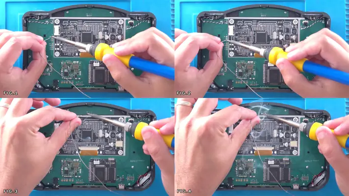
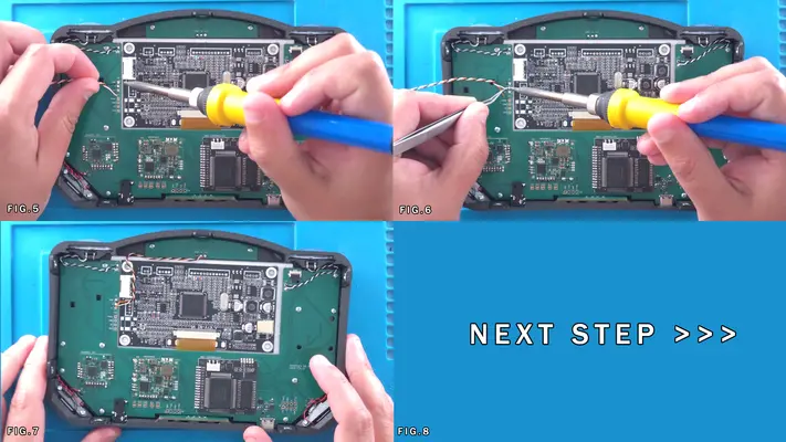
Wiring 3.3V & 5V Lines
STEP SUMMARY
In this step we will be wiring up the 3.3V and 5V lines to the N64. These lines will later connect to the main motherboard with the PMS and will send the correct and regulated power to the system. NOTE: Different board revisions may have different style caps or layout, but the they are still the same.
DIFFICULTY - EASY
TOOLS NEEDED
- SOLDERING IRON - WIRE STRIPPERS (or Teeth if you live on the wild side)
MATERIALS NEEDED
- TRIPLE TWISTED 30AWG W/W/G FOR 3.3V
- TRIPLE TWISTED 30AWG W/W/O FOR 5V
- SOLDER
- FLUX
PARTS NEEDED
- N64 MOTHERBOARD
STEP PROCESS
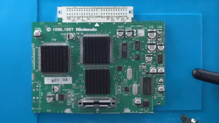
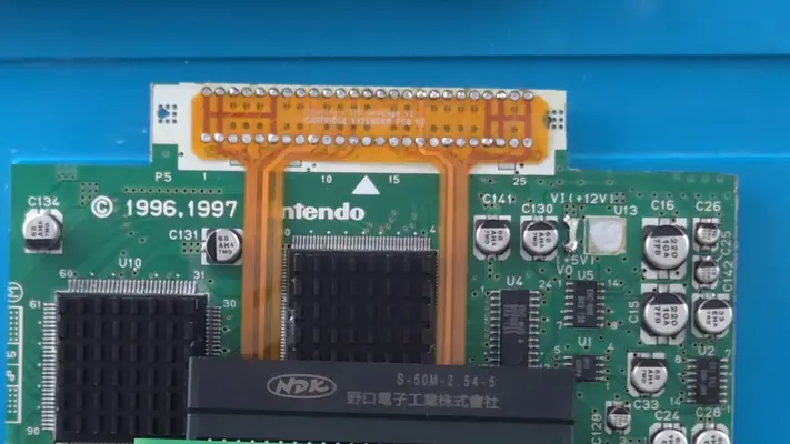
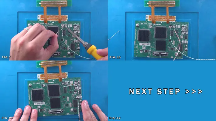
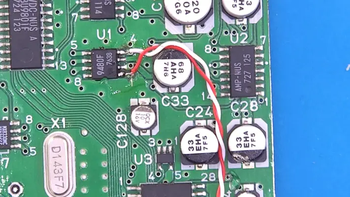
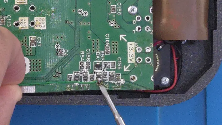
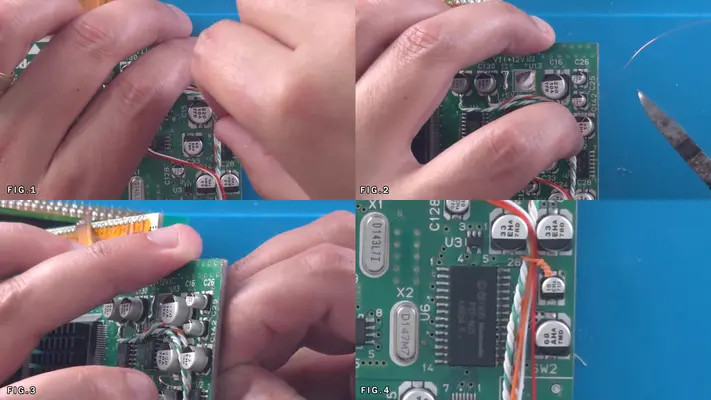
1. Look for caps C141 and C130 (Fig.2) These will be our solder points for 3.3V and 5v respectively.
2. At the base of each cap you will see a small solder point which we need to prep.
3. Apply a little bit of flux to both bases. Fig.5
4. Add a small amount of fresh solder to the base. Fig.6
5. Strip a small amount of the sheathing off one end of the W/W/G 3.3V set of wires, then twist them together to make a single strand. (Flatnose Pliers help a great deal with this). Then hit the wire with a bit of solder to make it solid.
6. Butt the wire right up to the solder on the base of cap C141 and hit it with the iron. Fig.7&8
7. Repeat these steps with the W/W/O 5V set of wires and solder to cap C136
8. Check to make sure the solder points are solid and are not shorting to any of the nearby vias!
9. Move the wires over to the right and feed them down between the other caps as shown in Fig.11
PROCEED TO NEXT STEP
Audio Wiring
STEP SUMMARY
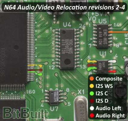
Wiring the audio is a fairly simple step, but depending on your version of the motherboard, maybe slightly different in the approach that is shown here. The rev used in this example was 2-4. See images to determine which board you have and the proper solder points.
DIFFICULTY - EASY
TOOLS NEEDED
- SOLDERING IRON
MATERIALS NEEDED
- TWISTED PAIR 30AWG R/W FOR AUDIO L&R
- SOLDER
- FLUX
PARTS NEEDED
- N64 MOTHERBOARD
STEP PROCESS
1. Determine which rev motherboard you have by matching the layout of the board to one of the images from the Bit Built guides. This will determine the correct solder points for your board. All we care about are Audio Left (white) and Audio Right (Red) markings
2 Fig.1-8 basically show the same process for rev's even though the position may be different.
3. Flux the pins, add a small amount of solder to the pin and/or via depending on version and solder the W/R to their respective pins.
4. Again, make sure the connection is solid and are not shorting anywhere.
5. Clean up any residue with Isopropal Alcohol and Q-Tip
6. Move the wire over and feed between the same caps as the 3.3V and 5V lines. PROCEED TO NEXT STEP
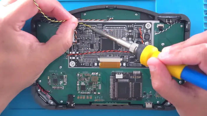
Video Wiring
STEP SUMMARY
Now though technically you could have wired the video from the same source as the audio in the last step, composite video is susceptible to interference and can cause signal distortion. By wiring to the original output that you would plug into your TV, we take advantage of the onboard filtering caps which gives us much better signal quality. This step is universal for all board revs.
DIFFICULTY - EASY
TOOLS NEEDED
- SOLDERING IRON - WIRE STRIPPERS
MATERIALS NEEDED
- TWISTED PAIR 30AWG Y/B FOR VIDEO/GND
- SOLDER
- FLUX - HOT GLUE GUN (OPTIONAL)
PARTS NEEDED
- N64 MOTHERBOARD
STEP PROCESS
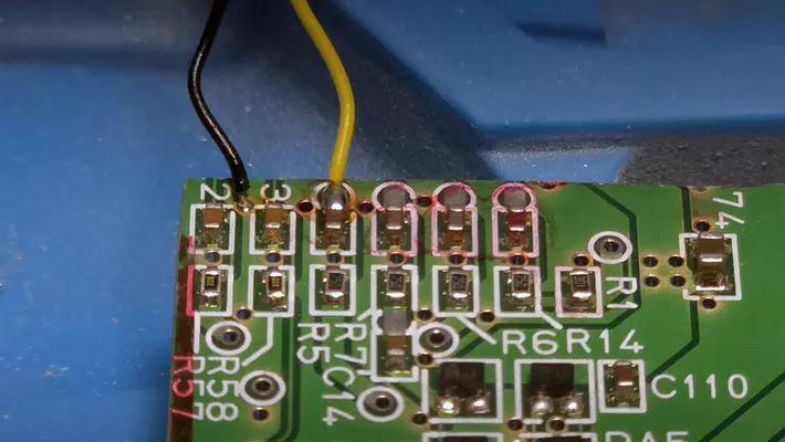
1. On the back of the board, locate the 3rd capacitor from the left. It should be the first one with a "test point" in front of it.
2. If you followed the trimming guide, that entire row of test points should be intact, however if you went in too deep, we may have to solder to another point and potentially lose the filtering caps.
3. Using the same wiring process as before, hit the test point pad/cap with flux and small amount of solder. Fig.2
4. Strip a very small amount of sheathing off both the Black and Yellow wires. Keeping the amount of exposed wire to a minimum will be critical here for the last step.
5. Solder the yellow wire to the pad and the Black wire to the ground via to the left of it as shown in Fig.6
6. Make sure the connections are solid and there are no shorts and then clean up flux residue with Isopropyl Alcohol. Though not shown, you can "pot" these connections in hot glue now if you like, keeping in mind though that you may need get at these points again later if video is not working, but it will help prevent shorts.
7. Fold the wire around to the top of the board and feed down between the same caps as the 3.3V, 5V and Audio lines. Fig.7
PROCEED TO NEXT STEP
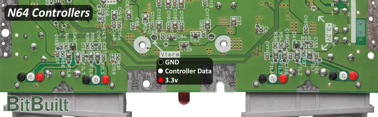
Wiring The Controller Data Line
STEP SUMMARY
Though the original controller had 3 lines, we only need to worry about the data line.
DIFFICULTY - EASY
TOOLS NEEDED
- SOLDERING IRON
- WIRE STRIPPERS
MATERIALS NEEDED
- 1 STRIP OF 30AWG GREEN ABOUT 12IN LONG
- SOLDER
- FLUX
PARTS NEEDED
- N64 MOTHERBOARD
STEP PROCESS
1. Because we trimmed off the through-hole pads, we need to wire to an alternative location.
2. Locate the DA1 diode.
3. Just below that is a cap with a test point which would read FIL2 if we didn't cut it off. But, hit the test point with some Flux and small amount of solder.
4. Again strip a small bit of sheathing and solder the wire to the test point/cap as shown.
5. Route the wire to the left to meet up with the rest of wires.
PROCEED TO NEXT STEP
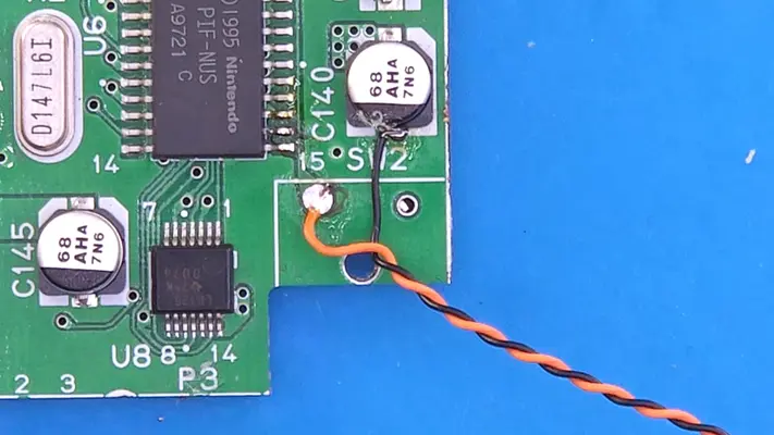
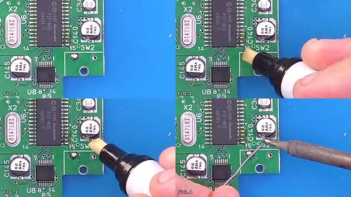
Wiring The Rest Button
STEP SUMMARY
The Reset Button is only needed if you plan to use Flashcarts like an Everdrive, but is recommended to install anyway.
DIFFICULTY - EASY
TOOLS NEEDED
- SOLDERING IRON
- WIRE STRIPPERS
MATERIALS NEEDED
- TWISTED PAIR 30AWG O/B ABOUT 12" LONG
- SOLDER
- FLUX
PARTS NEEDED
- N64 MOTHERBOARD
STEP PROCESS
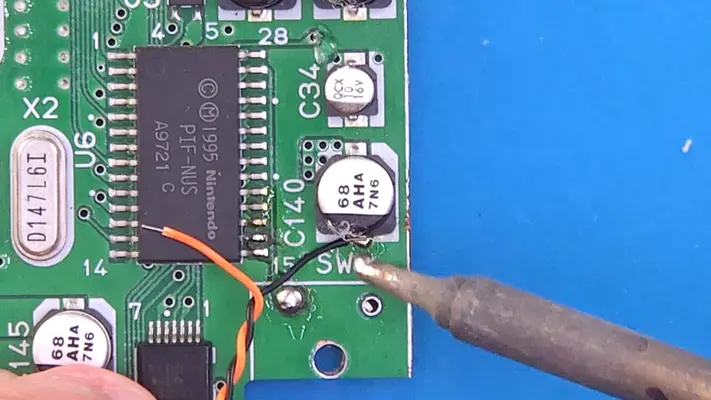
1. Same routine as before, locate the test point that was under the reset button that has a trace going up to the PIF chip.
2. Flux and Solder to the test point and also to the base of the cap just to the right as shown.
3. Strip a small amount of sheathing from both wires and solder the Orange to the test point and the Black to the cap.
PROCEED TO NEXT STEP
Wire Management
STEP SUMMARY
This last step is optional, but it makes keeping the build tidy and clean and is highly recommended.
DIFFICULTY - EASY
TOOLS NEEDED
- PLIERS
- CUTTERS
MATERIALS NEEDED
- SCRAP 34 AND 30AWG WIRE
PARTS NEEDED
- WIRED N64 MOTHERBOARD
STEP PROCESS
1. To really secure the wires to the motherboard, I use 34AWG wire to loop through the vias on the mother board tie it down to the board.
2. Alternately, you can take small strips of 30AWG and twist it together with pliers to to hold them all together. CONGRATS! THIS COMPLETES THE WIRING PORTION OF THE N64 MOTHERBOARD!
PART IV - CASE ASSEMBLY
This section we'll assemble the front and back halves of the enclosure.
- Inserting Square Nuts Into Traps
- Inserting Square Nuts Into Mounting Brackets
- Mounting The Brackets To The Back Face Bracket
- Adhering The Brackets To The Front Face Bracket
- Weeding The Vinyl Decal
- Adhering The Acrylic LED Face Plate
- Mounting The Decal To The Front Face Plate
- Mounting The Front Face Plate To The Front Face Bracket
- Mounting The Back Face Plate To The Back Face Bracket
- Mounting The Reset Tact Switch To The Cart Cover
OVERALL DIFFICULTY - MODERATE
CRITICAL STEP AND/OR SAFETY NOTICE
There will be use of super glue and other adhesives that can cause injury if they come into contact with your skin or eyes. Please use protective gloves and eyewear when doing these steps.
BACK TO TABLE OF CONTENTS
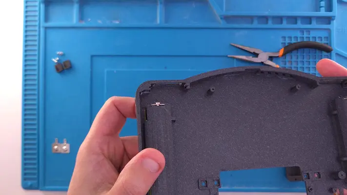
Inserting #2-56 Sq Nuts Into "Front Face Bracket" Traps
STEP SUMMARY
The first step in the case assembly process is to add the square nuts for the power/volume button board. This is a very easy step but one that is crucially important because if you forget to put these in you won't be able to after the front faceplate has been adhered.
***MAKE SURE THIS STEP IS COMPLETED BEFORE ADHERING THE "FRONT FACE PLATE" TO THE "FRONT FACE BRACKET"***
DIFFICULTY - EASY
TOOLS NEEDED
- PRECISION FLAT HEAD SCREW DRIVER
MATERIALS NEEDED
- NONE
PARTS NEEDED
- QTY (2) - BAG #1/G - #2-56 SQ NUT
- QTY (1) - 3D PRINTED - FRONT FACE BRACKET
-
STEP PROCESS
2. Make sure they are pushed all the way to the bottom and center well with the holes.
Mounting Square Nuts to Mounting Brackets
STEP SUMMARY
In this step will be adding the square nuts to the mounting brackets. These will allow us to open and close the case fairly easily later on down the road.
In most cases, if it's a little too tight, you can force it in with a set of flat pliers.
DIFFICULTY - EASY
TOOLS NEEDED
- FLATNOSE PLIERS
MATERIALS NEEDED
- GOOP (POSSIBLY)
- Q-TIP (POSSIBLY)
PARTS NEEDED
- QTY (7) - BAG #1/G - #2-56 SQ NUT
- QTY (7) - BAG #3/C - SIDE MOUTING BRACKETS
PROCEED TO NEXT STEP
Mounting Brackets To Back Face Bracket
STEP SUMMARY
Though not a difficult step, it has to be done carefully to ensure proper alignment of the case halves.
DIFFICULTY - MODERATE
TOOLS NEEDED
- #P2 PHILLIPS SCREW DRIVER
MATERIALS NEEDED
- NONE
PARTS NEEDED
- QTY (1) BACK FACE BRACKED - 3D PRINTED
- QTY (7) SIDE MOUNTING BRACKES W/SQ NUTS INSTALLED
- QTY (7) BAG #1/B - #2-56 X 1/4" FHMS
STEP PROCESS
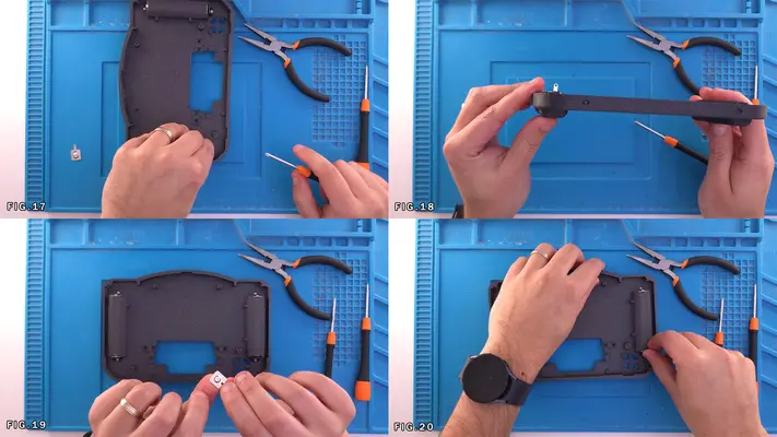
1. Locate the 7 recessed screw holes on the Back Face Bracket. 1 Top, 2 Left & Right, 2 Bottom
2. Take one Side Mounting Bracket and Black Machine Screw and attach the bracket as show in Fig. 3-5
3. Repeat these steps for the remaining 6 Brackets
4. Make sure each Bracket is perfectly straight as this will be critical for the next step. Fig. 9-12
PROCEED TO NEXT STEP
Adhering Mounting Brackets to Front Face Bracket
STEP SUMMARY
This is a fairly tricky part because we are working on a short time limit due to the speed in which super glue dries. You do have the option to use GOOP instead of super glue if you think you'll need more time, but super glues generally have a stronger bond and can sometimes even fuse the plastics together.
SAFTEY CHECK POINT
DIFFICULTY - HARD
TOOLS NEEDED
- NONE
MATERIALS NEEDED
- SUPER GLUE (CYANOACRYLATE OF SOME KIND)
- GOOP (OPTIONAL SECONDARY CHOICE)
PARTS NEEDED
- BACK FACE BRACKET W/SIDE MOUNTING BRACKETS ATTACHED - 3D PRINTED
- FRONT FACE BRACKET W/SQ NUTS IN TRAPS - 3D PRINTED
STEP PROCESS
1. Locate the 7 mounting channels on the Front Face Bracket.
2. Keeping the Front Face Bracket face down, add a single drop of Super Glue to the very center of each channel.
3. Keep it face down until it's time add the Back Face Bracket because we don't want the glue running towards the seam and potentially gluing the two halves together.
4. Carefully take the Back Face Bracket and feed the Mounting Brackets into the channel.
5. Now the clock is ticking. Make sure the case halves are meeting cleanly all the way around the case and no gaps between the two are showing.
6. Once it looks perfect, apply pressure to each tab individually until it's firmly attached to the bracket and reinforce if needed.
PROCEED TO NEXT STEP
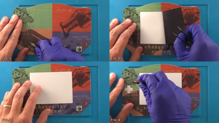
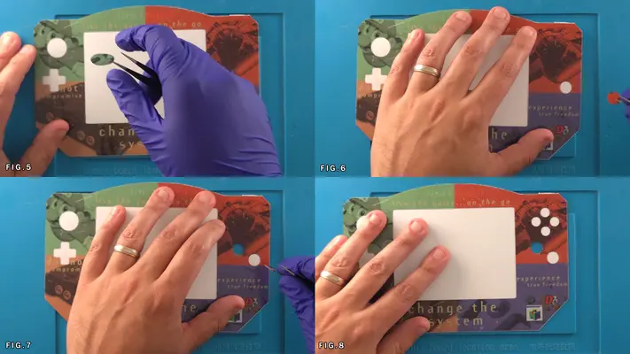
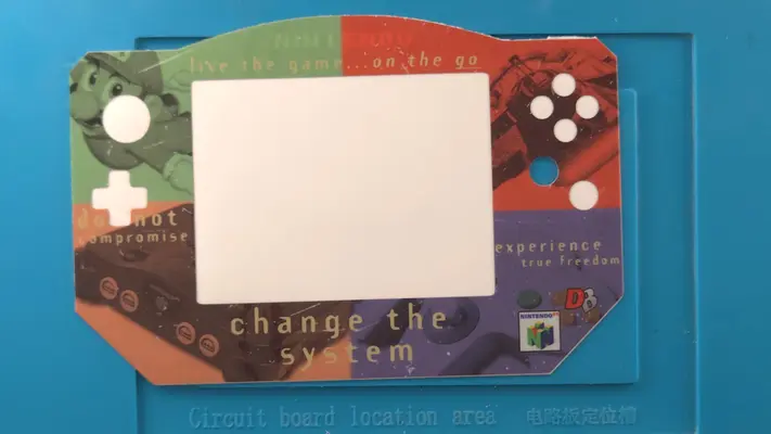
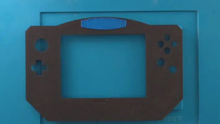
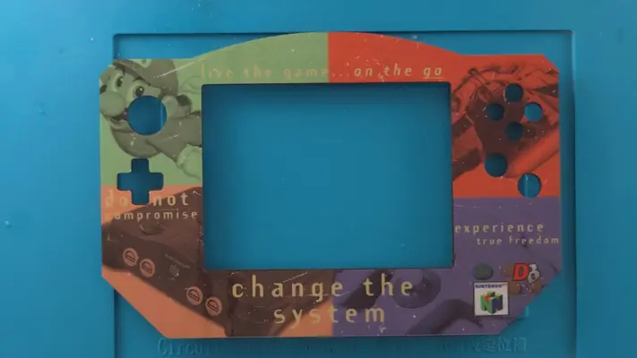
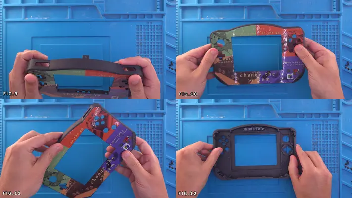
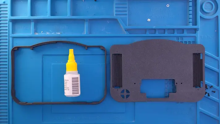
Weeding Front Face Decal
STEP SUMMARY
The Laminated Vinyl Decal will come flat on a sheet and will be pre-cut to match the Front Face Plate, but will need to be what we in the print business call, "Weeded".
DIFFICULTY - EASY
TOOLS NEEDED
- TWEEZERS
MATERIALS NEEDED
- NONE
PARTS NEEDED
- LAMINATED VINYL DECAL
3. Start with the screen cutout and work your way around, removing the D-Pad, Joy Con and the B/A/C buttons.
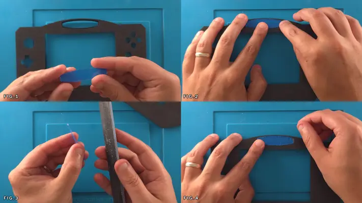
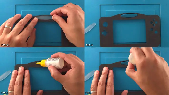
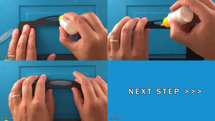
Adhering The Acrylic LED Lens To The Front Face Plate
STEP SUMMARY ***IMPORTANT STEP***
This piece of Acrylic acts mainly as a LED diffuser for the battery indicator/Nintendo logo and needs to be glued in place.
SAFTEY CHECKPOINT
PROTECTIVE GLOVES HIGHLY RECOMMENDED FOR THIS STEP!
DIFFICULTY - EASY
TOOLS NEEDED
- 80 GRIT NAIL FILE
MATERIALS NEEDED
- SUPER GLUE
PARTS NEEDED
- QTY (1) - BAG #6 - ACRYLIC SPACER
- QTY (1) - FRONT FACE PLATE - 3D PRINTED
STEP PROCESS
PROCEED TO NEXT STEP
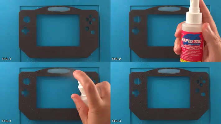
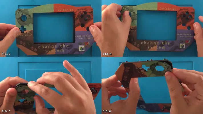
Mounting Decal To Front Face Plate
STEP SUMMARY
Mounting any kind of adhesive decal can actually be a fairly challenging and frustrating part any project, but following these steps and having the right materials will make this process so much easier.
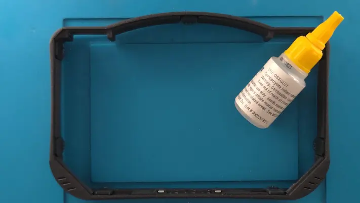
Though this decal is laminated and is resistant to stretching and tearing, it is still a self-adhesive material which means as soon as it touches a surface, it wants to stay there. Rapid Tac is a cheap but highly effective fluid that both cleans the surface and allows for easy repositioning of the decal to line it up just right and I highly recommend picking up a small bottle.
DIFFICULTY - MODERATE
TOOLS NEEDED
- SQUEEGE OR PAPER TOWLES
- X-ACTO KNIFE OR OTHER PRECISION CUTTING TOOL
MATERIALS NEEDED
- RAPID TAC
PARTS NEEDED
- QTY (1) - WEEDED VINYL DECAL
- QTY (1) - FRONT FACE PLATE W/ACRYLIC INSERT
STEP PROCESS
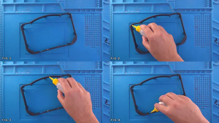
1. Spray the surface of the Front Face Plate with a generous amount of Rapid Tac until the entire surface is covered as shown in Fig. 3&4
3. Start from the left side and line up the Joy Con hole and the dpad as best you can and work your way across to the other side. The cut for the screen is slightly off so you will see a small sliver of plastic on the right side, but the important part is making sure all the holes line up.
4. Once everything is lined up correctly, squeeze out the Rapid Tac by taking a paper towel (Fig.10) and press against the decal so the liquid comes out the sides. Once this is done, what's left over will begin to dry, bonding with the glue and the Front Face Plate and your decal will be adhered.
PROCEED TO NEXT STEP

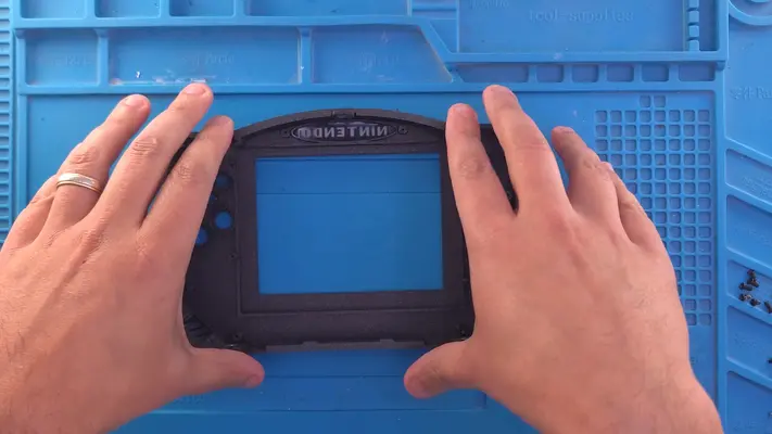
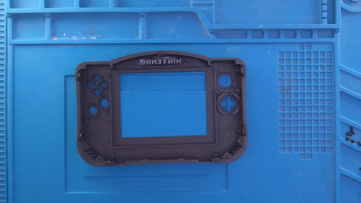
Mounting Front Face Plate to Front Face Bracket
STEP SUMMARY
In this step we will be mounting the Front Face Bracket to the Front Face Plate in preparation to build the Front Face Assembly. A simple step, yet again requires the use of Super Glue so we have to work quickly.
SAFETY CHECK POINT PROTECTIVE GLOVES ARE HIGHLY RECOMMENDED
DIFFICULTY - EASY
TOOLS NEEDED
- NONE
MATERIALS NEEDED
- SUPER GLUE
PARTS NEEDED
- QTY (1) - FRONT FACE BRACKET W/MOUNTING TABS - 3D PRINTED
- QTY (1) - FRONT FACE PLATE WITH DECAL - 3D PRINTED
STEP PROCESS
1. As shown in Fig. 1-6, hit the entire inner lip with a bead of Super Glue. Make sure every flat surface has a little bit of glue on it.
2. After, carefully take the Front Face Plate and place into the bracket.
3. Apply even pressure to all sides until the glue cures. It should feel like one solid piece and all the walls should be tightly adhered to the plate. Reinforce if needed.
PROCEED TO NEXT STEP
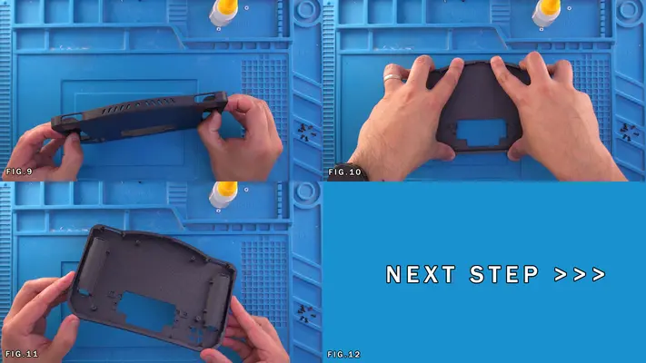
Mounting Back Face Plate to Back Face Bracket
STEP SUMMARY
This is the exact same procedure as the last step, just with the Back Face Bracket and Back Face Plate.
DIFFICULTY - EASY
TOOLS NEEDED
- NONE
MATERIALS NEEDED
- SUPER GLUE
PARTS NEEDED
- QTY (1) - BACK FACE BRACKET - 3D PRINTED
- QTY (1) - BACK FACE PLATE - 3D PRINTED
STEP PROCESS
1. Just like the last step, hit the lip with Super Glue and apply even pressure to the plate. There should be no loose corners or moving walls and should feel like one solid piece. PROCEED TO NEXT STEP
PART V - PREPARING THE CUSTOM PCBs
- Installing The PMS Module
- Finishing and Cleaning The Modules
- Preparing The 3rd 18650 Battery Holder
The good thing here though is that the pitch of all the pins/pin pads is relatively large in comparison to some of the more complicated mods and can be pretty forgiving if you have to try again.
OVERALL DIFFICULTY - MODERATE
CRITICAL STEP AND/OR SAFETY NOTICE
NOTE - THE FINAL PRODUCTION VERSION OF THE MAIN MOTHERBOARD PCB THAT IS INCLUDED IN THE KIT IS BLACK, BUT YOU WILL NOTICE THE SOLDER PADS FOR THE CONTROLLER MODULE AND THE AUDIO MODULE HAVE WHAT LOOKS LIKE A SOLDER PASTE ALREADY ON THEM. THEY CAME THIS WAS FROM THE MFG I THINK IN ERROR, BUT SHOULDN'T CAUSE A PROBLEM.
START WITH ONE PAD AND SEE HOW IT LOOKS. IF IT HOLDS WELL WITHOUT THE NEED FOR ADDITIONAL SOLDER THAN GREAT! IF NOT, IT'LL BE NO DIFFERENT THAN IF IT HAD NO PASTE AT ALL.
BACK TO TABLE OF CONTENTS
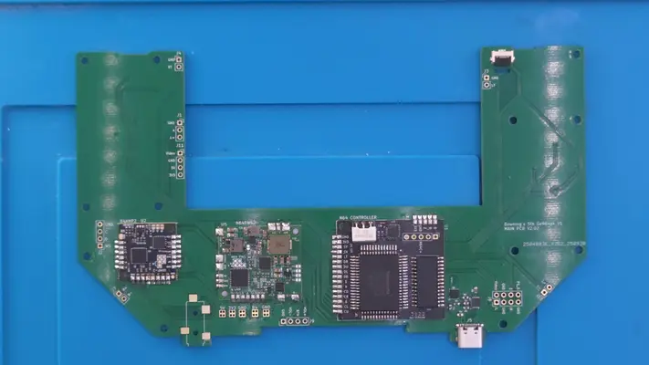
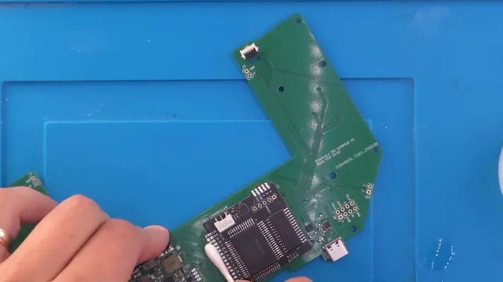
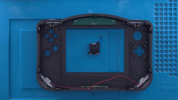
Installing The Controller Module
STEP SUMMARY
The controller module is the condensed version of an actual N64 controller. In fact, the main control chip came out of an original 1st party controller. It also has a built in FRAM chip for non-volatile memory card.
It's very important that you take your time with these steps because you have very tight tolerances to hold to avoid shorts and once these are soldered to the board, they are very difficult to remove.
DIFFICULTY - MODERATE
TOOLS NEEDED
- SOLDERING IRON
MATERIALS NEEDED
- SOLDER
- FLUX
PARTS NEEDED
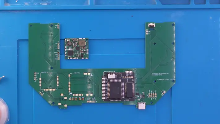
- QTY (1) - 5TH GEN64 MAIN MOTHER BOARD - PCB
- QTY (1) - N64 CONTROLLER MODULE
STEP PROCESS
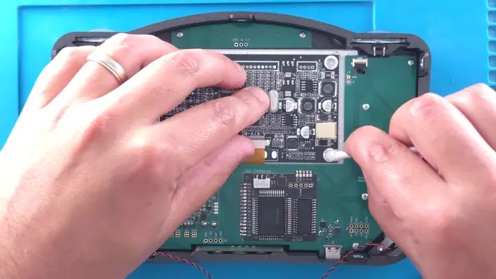
1. Start by applying Flux to the pads on the N64 Controller section as shown in Fig. 1-3.
2. Apply solder to one pad as shown in Fig. 5 and line up the control module to the matching pad.
3. Solder the pads together and rotate the whole motherboard so you can easily access the other pads.
4. Align the pads and tack it in place by soldering another single pad.
5. Again, depending on your skill level, you can solder pin to pin one at a time, or you can use the heat and drag method. Either way, make sure all the pads on are soldered in place.
6. Next, take the Flux once again and go over all the pads again as shown in Fig. 12.
7. Hit the pads again with the soldering iron which should clean up and leave a nice bead of solder on each pin.
8. Give each pin a good close inspection to make sure no pins are bridged together and there are no shorts. Repeat the Flux and Heat if so until clean.
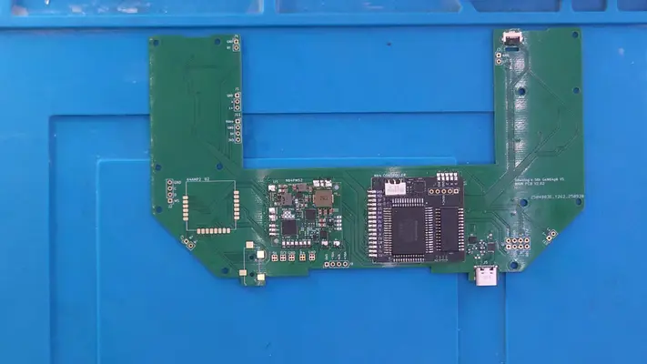
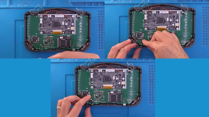
Installing The PMS
STEP SUMMARY
The N64 PMS is a 4 Layer Tech innovation that takes all the guess work out of Power Management. This takes care of charging the batteries and making sure the voltages are regulated. Truth be told it does far more than that and is a remarkable piece of tech!
It also has another neat feature though in that it allows you to choose your charge rate through a series of jumpers on the PMS itself. The default rate is set to 1A, which when you have over 9A of total power between the 3 batteries, doing the math, you see that's gonna take a long time. With this board you have the option to choose 1A, 2A, 3A or 4.5A charge rates, which means fully cranked, will charge the portable in less than 2hrs.
Check out the full specs here at 4 Layer's N64 PMS
Installation is exactly the same as the Controller Board.
DIFFICULTY - MODERATE
TOOLS NEEDED
- SOLDERING IRON
MATERIALS NEEDED
- SOLDER
- FLUX
PARTS NEEDED
- QTY (1) - 5TH GEN64 MAIN MOTHERBOARD - PCB
- QTY (1) - BAG #2 - N64PMS MODULE
STEP PROCESS
1. Employ the same process and the controller board. PROCEED TO NEXT STEP
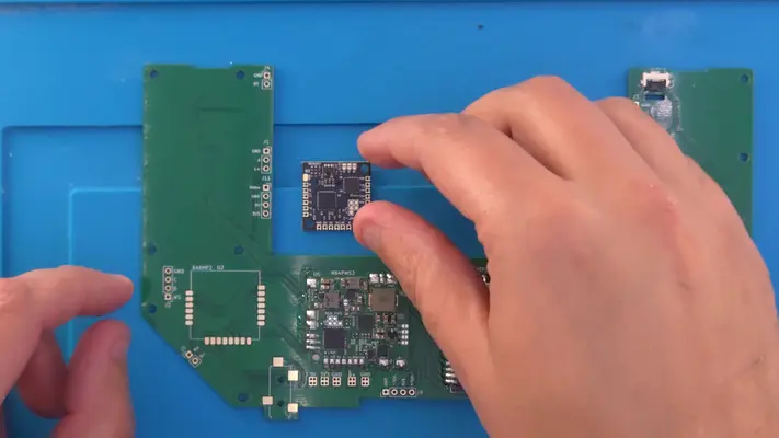
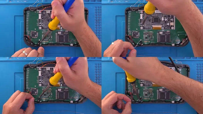
Installing The Audio Amp
STEP SUMMARY
The UAMP-2 is another 4 Layer Tech product which controls all audio functions for a variety of different consoles. Our specific use will be for its analog capabilities, which means we have to configure at jumper on the module otherwise we'll get no sound at all.
For more detailed info on the board, See 4 Layer's Specs of the U-AMP 2 Here.
Installation is exactly the same as the previous two modules, however you will notice that in this case, the module is upside down which is correct.
DIFFICULTY - MODERATE
TOOLS NEEDED
- SOLDERING IRON
MATERIALS NEEDED
- SOLDER
- FLUX
PARTS NEEDED
- QTY (1) - 5TH GEN64 MAIN MOTHERBOARD - PCB
- QTY (1) - BAG #2 - U-AMP 2 PCB
STEP PROCESS
1. As stated before, the soldering process is the same as the previous 2 steps, with one exception.
2. Once the Amp is soldered to the main board, find the pad on the AMP labeled J2
3. Using a bead of solder, connect the two pads and this will enable "Analog" mode on the Amp.
PROCEED TO NEXT STEP
Finishing and Cleaning Up The Module
STEP SUMMARY
Now that we're done making a Fluxy mess, we need to clean it up. Isopropyl Alcohol and Q-tips are our friend here.
DIFFICULTY - EASY
TOOLS NEEDED
- NONE
MATERIALS NEEDED
- ISOPROPYL ALCOHOL
- Q-TIPS
PARTS NEEDED
- QTY (1) 5TH GEN64 MAIN MOTHER BOARD - POPULATED
STEP PROCESS
1. Like the clean up we did while prepping the N64 motherboard, we have to do the same here. Carefully remove all the Flux residue with the ISO and Q-Tips until you have nice shiny looking solder pads.
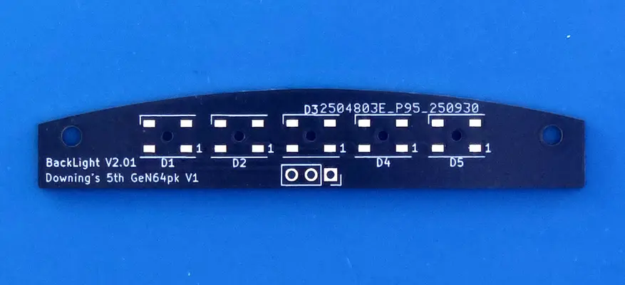
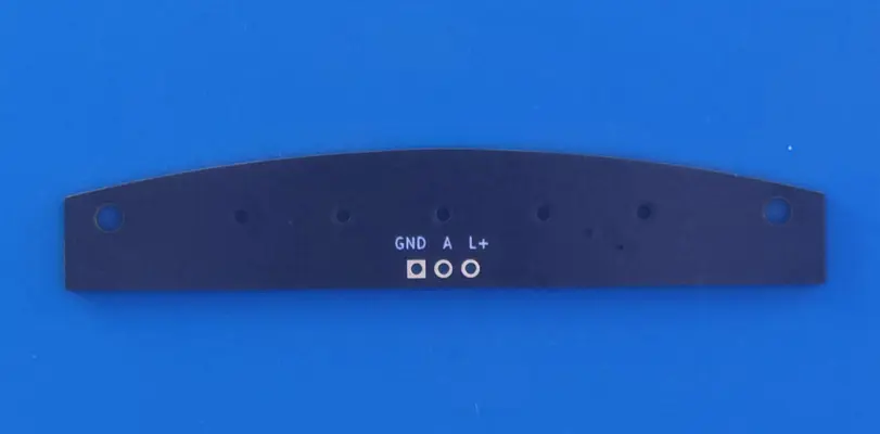
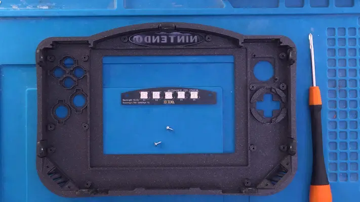
Preparing The LED Backlight Board
STEP SUMMARY
Though this step looks unassuming enough, it's actually a real pain in the rear that actually earns a HARD difficulty rating. The main issue is with the LED's themselves, as they are surface mount, designed for solder paste and a reflow oven. In the future these may very well end up being a manufactured board and this step can go away, but for now, get ready for a "fun" time.
DIFFICULTY - HARD
TOOLS NEEDED
- SOLDERING IRON
- NEEDLE NOSE PLIERS or TWEEZERS
MATERIALS NEEDED
- SOLDER
- FLUX
PARTS NEEDED
- QTY (1) - BAG #2 - BACKLIGHT PCB
- QTY (5) - BAG #6 - WS2812B - RGB LEDS
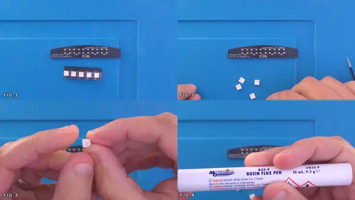
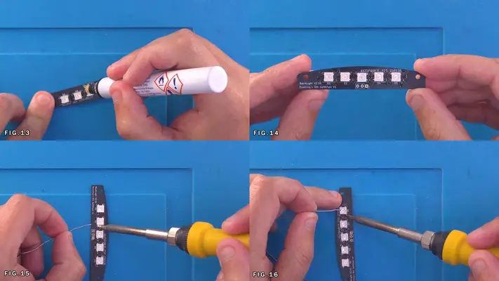
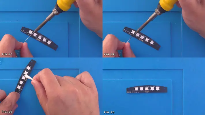
STEP PROCESS
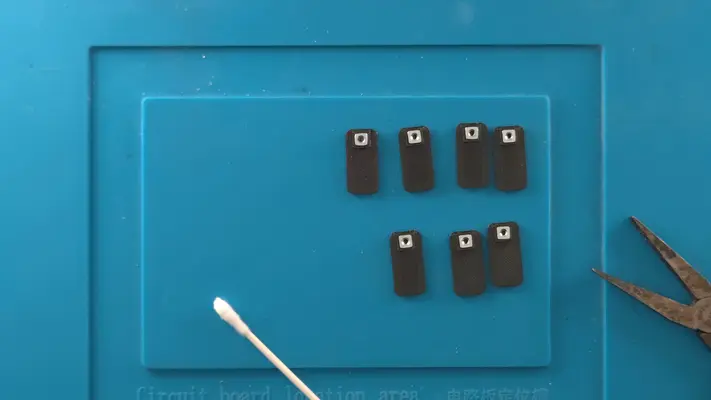
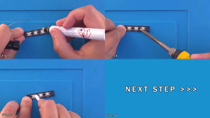
1. Remove the LEDs from the cut-tape and arrange them all in the same orientation with marked corner in the top left. See Fig. 3
2. Flux all the pads.
3. Put a small amount of solder onto your soldering iron directly and as shown in Fig. 8, hit the top right pad of every LED foot print. This will allow us to tack the LED in place while still granting a little bit of movement to align it correctly.
4. Place the LEDs down inline, taking them in place on the right while checking again to make sure the mark on the LED is in the top left.
5. Once the LEDs are tacked, Flux the very small pins on the LED's themselves as show in Fig.13
6. Adding small amounts of Solder to your iron, go around and hit the pins and pads of the rest of the LED board, being careful to not melt the plastic on the LEDs. This is the hardest part. 7. Once complete and the LEDs are securely soldered, clean up the Flux residue like we did in the previous steps. PROCEED TO NEXT STEP
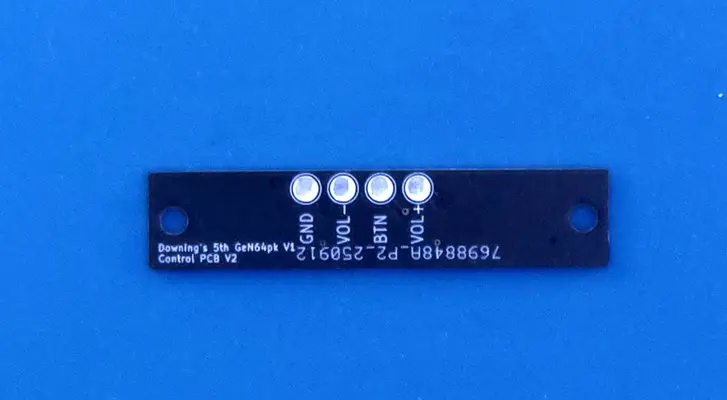
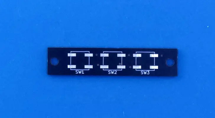
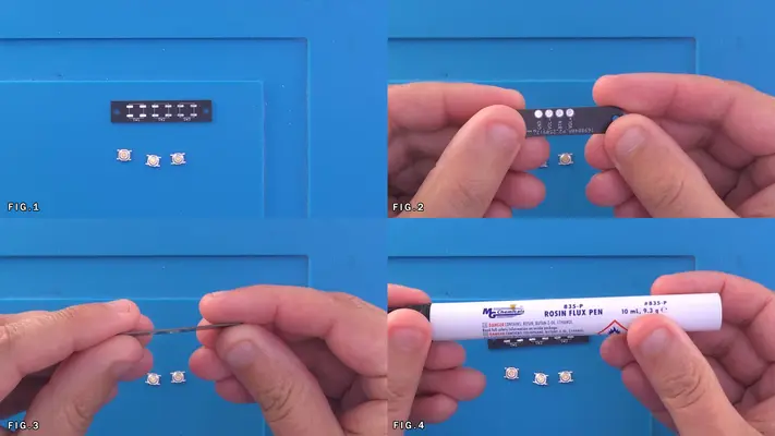
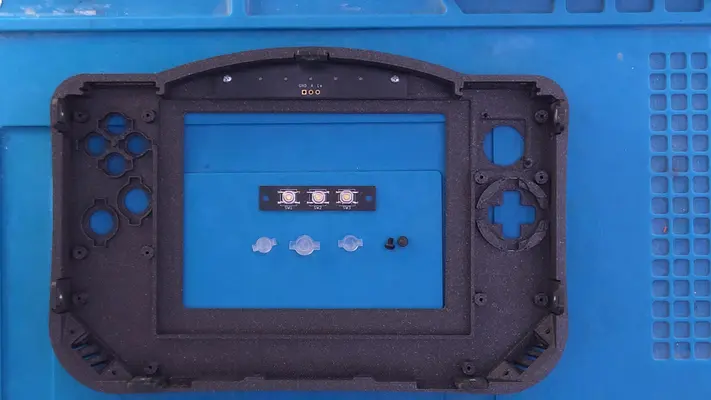
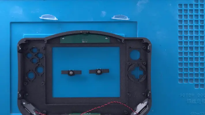
Preparing The Power/Volume Buttons & PCB
STEP SUMMARY
The Power/Volume Button Board is another simple, yet tricky board to assemble. Though not as bad as the LED board, we are still dealing with very small surface mount components that can be a bit of a pain to work with.
DIFFICULTY - MODERATE
TOOLS NEEDED
- SOLDERING IRON - NEEDLE NOSE PLIERS
MATERIALS NEEDED
- SOLDER
- FLUX
PARTS NEEDED
- QTY (1) - BAG #2 - BUTTON BOARD PCB
- QTY (3) - BAG #6 - CKN12221-1-ND - LOW PROFILE TACT SWITCH
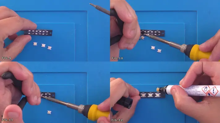
STEP PROCESS
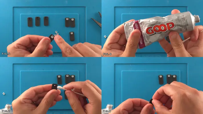
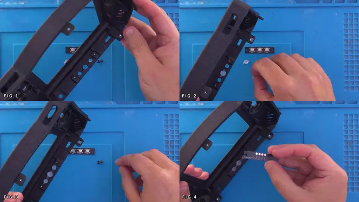
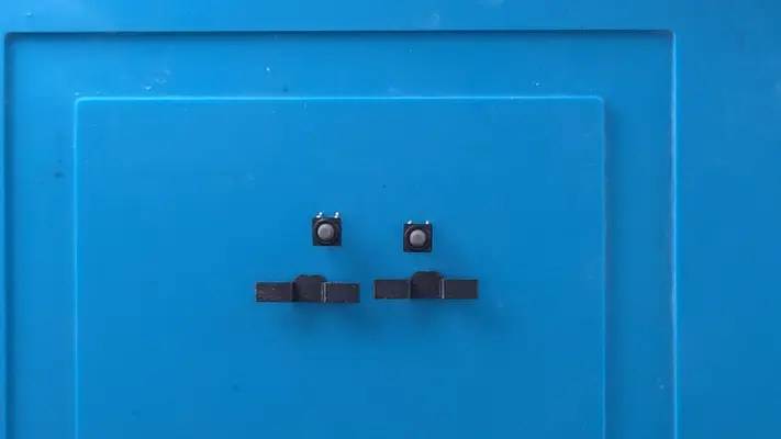
1. Remove the PCB and tact switches from their respective bags.
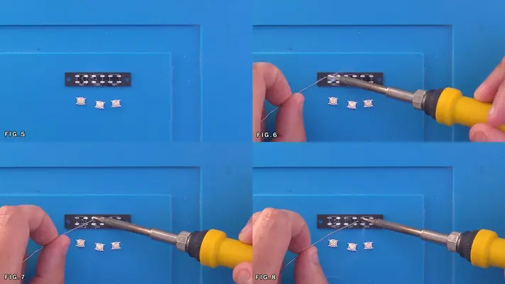
2. Flux the pads on the SW1, SW2 and SW3 side of the PCB. Fig.4
3. Unlike with the LEDs, these tact switches have legs that are easy to hit with the iron, so you can hit all 12 pads with solder upfront.
4. Working your way left to right (if you're righty), place each tact as close to center of the box as you can get. This is important because if you are too far off center, the buttons will not press correctly later on.
5. Once all the pins have been soldered, hit them with FLUX again (Fig. 12&13) and then the iron to give the joint a nice clean and even finish.
6. As we did with the other PCBs, then clean the Flux residue with ISO and a Q-Tip.
PROCEED TO NEXT STEP
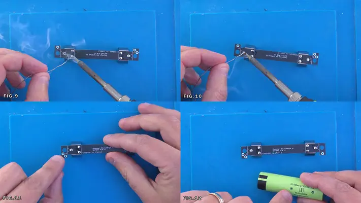
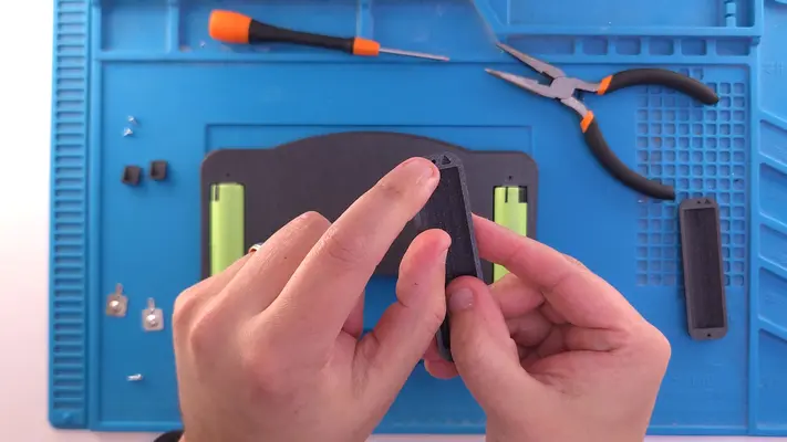
Preparing The 3rd 18650 Battery Holder
STEP SUMMARY
The 3rd battery is is a bit more involved though is still pretty straight forward. This whole assembly only consists of 4 parts, but you have to take up as much slack as possible when you solder, which we'll get into in detail.
DIFFICULTY - MODERATE
TOOLS NEEDED
- SOLDERING IRON
- MULTIMETER
MATERIALS NEEDED
- SOLDER
PARTS NEEDED
- QTY (1) - BAG #2 - BATTERY PCB
- QTY (2) - BAG #6 - 36-54-ND - 18650 BATTERY CLIP
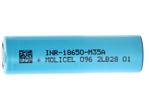
- QTY (1) - 18650 BATTERY (NOT INCLUDED)
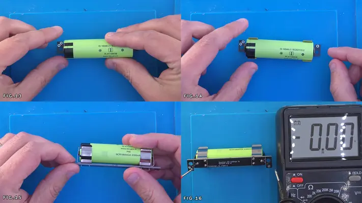
STEP PROCESS
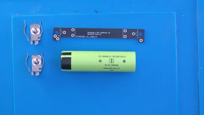
1. Remove the components from their respective packages.
2. Take the Battery PCB and flip it over as shown in Fig.5
3. Take the battery clips and insert them as shown in Fig.6 and flip the board back over as shown in Fig.7
4. Make sure the pins of the clip are pushed as far to the right as they can go as shown in Fig.8 before soldering them in place. This will help keep the battery as tight as possible.
5. Rotate the board 180 and repeat the step with the other clip.
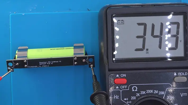
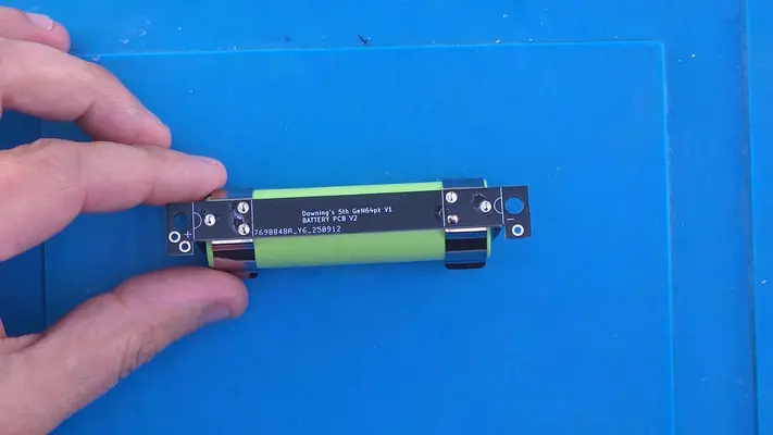
6. Once the clips are soldered, you can add the battery, but we have to make sure that we have the polarity correct.
7. As shown in Fig.11, the positive (+) side of the board has 2 thru-hole solder points we'll be using later and the negative (-) side has only one. We need to be sure that our battery is inserted the correct way.
8. All 18650 cells should be marked with a + or - and you of course need to match the two on the Battery PCB. Place the cell into the clips.
9. Double check with a multimeter as shown in Fig.16-17 by placing the positive lead to the + mark on the PCB and black to the negative. You should get a reading of 3.5v to 4v on the cell. If you get a -3.5v to -4v, you've got the cell in backwards and need to flip it!
PROCEED TO NEXT STEP
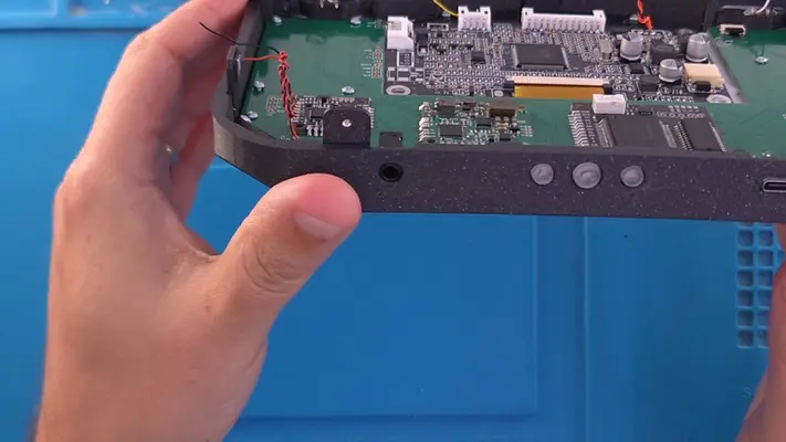
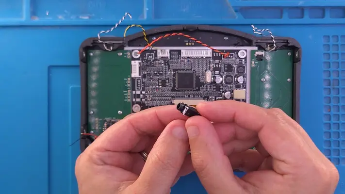
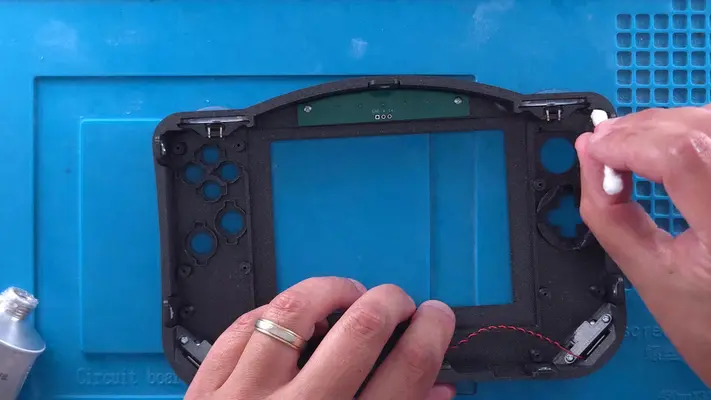
Mounting The Headphone Jack
STEP SUMMARY
Now this step is actually easier to do once the Front Face Assembly is complete, however PCB prep technically isn't complete until this jack is added to the Main PCB, so we're putting it in this section. The images show a lot more complete than we've covered to this point because that's how this one was put together. You can either wait until the Front Face Assembly is complete or do it now.
DIFFICULTY - EASY
TOOLS NEEDED
- SOLDERING IRON
MATERIALS NEEDED
- SOLDER
PARTS NEEDED
- QTY (1) - BAG #2 - HEADPHONE JACK PACKED WITH U-AMP
- QTY (1) - 5TH GEN64 MAIN MOTHERBOARD - PCB
STEP PROCESS
1. Having the Main Motherboard mounted into the Front Face Assembly helps a great deal with the alignment of the headphone jack, which is why you can choose two wait until that portion is complete. However, you can still simply place the board in the case half and accomplish the same thing.
2. Place the jack into the hole in the front face bracket. It go in a little hard, but it should snap down into place with the 4 legs touching the pads on the Main Motherboard.
3. Solder each leg to the pads.
PROCEED TO NEXT STEP
PART VI - THE FRONT FACE ASSEMBLY
- Mounting The Speakers
- Installing The LED Backlight
- Preparing & Installing The R/L Buttons
- Painting The SLA Printed Buttons (Optional)
- Preparing & Installing The Buttons & Button Pads
- Preparing & Installing The Display Driver Board
OVERALL DIFFICULTY - EASY

Installing The LED Backlight
STEP SUMMARY
Mounting the LED board is much much easier than it was to put the LEDs on it!
DIFFICULTY - EASY
TOOLS NEEDED
- P1 PHILLIPS SCREW DRIVER
MATERIALS NEEDED
- NONE
PARTS NEEDED
- QTY (2) - BAG #1/D or H - #1 X 3/16" PHMS - QTY (1) - BACKLIGHT LED BOARD - POPULATED
STEP PROCESS
1. Flip the LED PCB over so the LEDs are facing the Nintendo Logo.
2. Find the two standoffs on the case and match them with the screw holes on the PCB.
3. Screw them both into the standoffs. PROCEED TO NEXT STEP
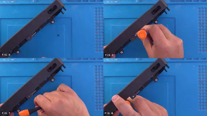
Installing The Power/Volume Buttons & PCB
STEP SUMMARY
Much like the LED board, this PCB is mounted in place by just two screws, however, in addition, we have to juggle the main power and volume buttons. Now, if you wish to paint these buttons first, skip ahead to the "Painting Buttons" section first before returning back to this step.
DIFFICULTY - EASY
TOOLS NEEDED
- P1 PHILLIPS SCREW DRIVER
MATERIALS NEEDED
- NONE
PARTS NEEDED
- QTY (1ea) - BAG #5/G - VOLUME +/- BUTTON - SLA 3D PRINTED
- QTY (1) - BAG #5/C - PWR BUTTON - SLA 3D PRINTED
- QTY (1) - CONTROL BOARD PCB - POPULATED - QTY (2) - BAG #1/F - #2-56 X 1/8" PHMS
STEP PROCESS
1. Locate the 3 holes on the front face bracket.
2. Place the Power Button in the center position (it won't fit anywhere else) Fig.2
3. Place the Volume (-) button into the left hole as if you were holding the console while playing. 4. Repeat with the (+) button on the opposite side.
5. Flip the Control Board PCB so that the tact switches are facing the buttons, and then rotate the board so the 4 solder points are facing away from the screen cut as seen in Fig.5
6. Line the board up with the screw holes for the nut traps and mount the board in place with the two screws.
7. Make sure the board is tightly secured and give all three buttons a few good test pushes, making sure they click clean, clear and freely without feeling tight or hard to press. If so, you may have to make a few adjustments to either the PCB placement, or even how tight you have it screwed into place.
8. Once the presses feel good and consistent, we can then move onto the next step.
Mounting The Speakers
STEP SUMMARY
Mounting the Speakers is a simple step that gets us that much closer to a fully populated "Front Face Assembly"
DIFFICULTY - EASY
TOOLS NEEDED
- P1 PHILLIPS SCREW DRIVER
MATERIALS NEEDED
- NONE
PARTS NEEDED
- QTY (4) - BAG #1/D or H - #1 X 3/16" PHSMS
- QTY (2ea) - BAG #3/B - SPEAKER MOUNTS & ADHESIVE FOAM PADS
- QTY ( 2) - BAG #6 - SP-15511L - WIRED SPEAKERS
STEP PROCESS
1. Remove the Speakers from their package and then remove the adhesive backer on the Foam Pads as seen in Fig. 2&3
2. Though Fig.4 & 5 show placing the pads on the Speaker Mounts, it was found later it actually is easier to stick the pad to the back of the SPEAKER ITSELF. This changes this step up a little bit and it will be corrected at a later date, though either way still get's the job done.
3. Locate the Speaker traps on the Front Face Bracket and Place the Speakers w/Pads attached, into them, one on each side, with the speakers wires facing in Fig. 9-11
4. Grab one of the Speaker Mounts and a #1 x 3/16" screw and start the screw into the Mount, just enough so the tip comes out the back a little bit. This will help with alignment when we go to screw it into the case.
5. The Speaker Mount needs to be aligned with the lip facing down and towards the speaker. Fig.14
6. Before we screw them in place, feed the one side of the Mount between the black and red wires of the speaker. Fig.14 & 15
7. Making sure the lip of the Mount is holding on to the bottom of the Speaker firmly, screw the Mount in place.
8. Repeat these steps for the other side. PROCEED TO NEXT STEP
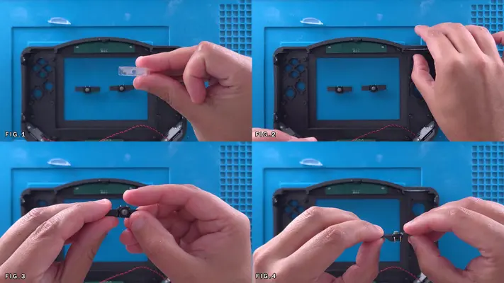
Preparing The R/L/Z Buttons
STEP SUMMARY
Though the Front Face Assembly only needs the R/L buttons, the Z buttons on the back face have the exact same set-up and it's easier to prepare all of them now.
DIFFICULTY - EASY
TOOLS NEEDED
- NONE
MATERIALS NEEDED
- GOOP
- Q-TIPS
PARTS NEEDED
- QTY (4) - BAG #6 - 8X8X5MM SOFT TOUCH TACT SWITCHS
- QTY (4) - BAG #3/E - SOFT TACT SWITCH HOLDER - 3D PRINTED
STEP PROCESS
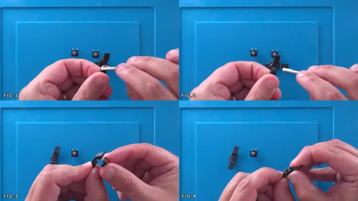
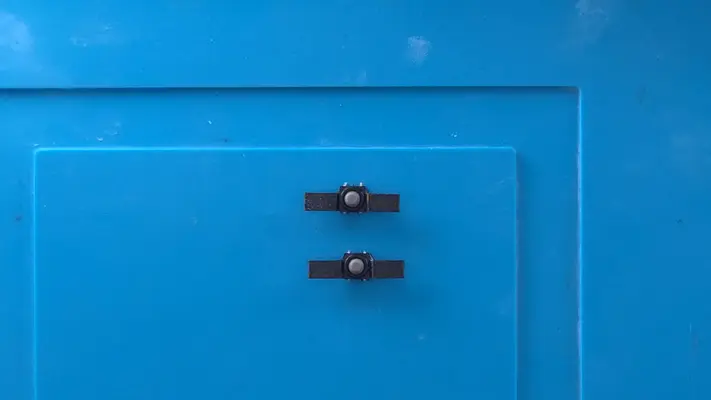
1. Apply a small amount of Goop to the center of the Soft Tact Switch Holder. Fig. 1&2
2. Place the Soft Tact Switch into the holder and press down to make sure the Goop bonds well.
3. Check and make sure no Goop has gotten up to the rubber of the switch itself as that can cause issues down the road.
4. If all clean, repeat this step for the rest of the buttons and set two aside for the Back Face Assembly a bit later on. PROCEED TO NEXT STEP
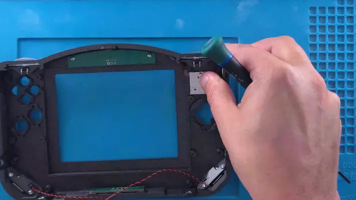
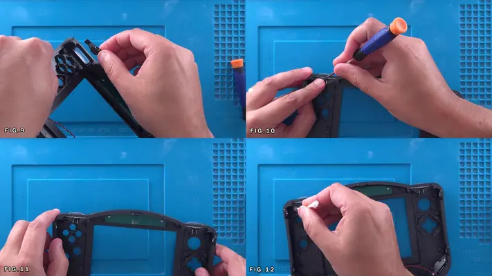
Installing The R&L Buttons
STEP SUMMARY
This step can potentially be a little tricky due to the tight tolerances of where the tact switches have to fit over the buttons. The important part is to make sure the button feels right after it's been installed and does not feel "stiff" or "tight" in any way. This could mean having to sand down the button base a little.
DIFFICULTY - MODERATE
TOOLS NEEDED
- PRECISION FLAT HEAD SCREWDRIVER
- SAND PAPER/NAIL FILE (MAYBE)
MATERIALS NEEDED
- GOOP
- Q-TIP
PARTS NEEDED
- QTY (2) - BAG #5/D - R & L BUTTON CAPS - SLA 3D PRINTED
- QTY (2) - ASSEMBLED SOFT TACT SWITCH MOUNTS
STEP PROCESS
1. With either the R or L button, do a test fit into the button cutout to make sure it fits cleanly and there are no burrs or obstructions that can get caught. The buttons will likely have small burrs on them from the SLA printing process so sanding these down could be necessary. Fig. 1
2. Repeat this for the other side and once all have been confirmed to freely move, leave the button in the cutout. NOTE: MAKE SURE THE BUTTON HAS THE LETTER FACING THE CORRECT DIRECTION AND WILL BE ON THE CORRECT SIDE! WITH THE CASE FACING THIS WAY FOR INSTALL, RIGHT IS LEFT!!!
3. Take one of the assembled mounts and flip it so the switch faces the button and overhang faces down. Fig.3 & 4
4. Carefully insert the mount into the side channels, stopping once the tact switch itself makes contact with button. Fig.5
5. The tricky part here is compress the switch actuator while pushing the switch mount into position, while keeping the button itself in place. This can be done using a precision Flat Head Screwdriver to gently compress the switch while also holding the button in place, allowing your other hand to push the assembly into position. Fig. 6
6. The channel has built in stops, so once you feel the assembly stop, you should be perfectly aligned.
7. Once the whole button assembly is in place, give the button as many test presses as you like to make sure it's to your liking, not tight and responsive. OPTION: If you think you need more clearance or want a bit more movement in the press, now is the time. Remove the assembly the same way it was installed, and on a flat surface, sand down both the base of the button and the tops of the two fins on either side of it. Doing so will give you a bit more clearance for your button presses.
8. If you are satisfied with how things feel, repeat the steps for the other side.
9. Once completely satisfied, take a small amount of Goop on a Q-Tip and roll it against the Tact Mount and the Channel at all 4 contact points. Fig. 12
PROCEED TO NEXT STEP If you came back to this step from the "Installing The Z Buttons" on the Back Face Assembly, Click Here to Return
Mounting The Joy Con
STEP SUMMARY
Although this took forever to really "dial" in the design, the installation process is now a breeze because of it and is done with just two screws.
DIFFICULTY - EASY
TOOLS NEEDED
- P1 PHILLIPS HEAD SCREWDRIVER
MATERIALS NEEDED
- NONE
PARTS NEEDED
- QTY (1) - BAG #6 - JOYCON - QTY (2) - BAG #1/D or H - #1 X 3/16" PPHMS
STEP PROCESS
1. Flip the Joy Con over making sure the the ribbon is facing up. Fig.1
2. Insert the Joy Con into the cutout and onto the standoff printed into the Front Face Plate.
3. Gently screw the Joy Con in place using its built in mounting brackets, being careful to to crank down too tight as they can break easily.
4. Flip the case over and the Joy Con should be centered nicely in the cutout. PROCEED TO NEXT STEP
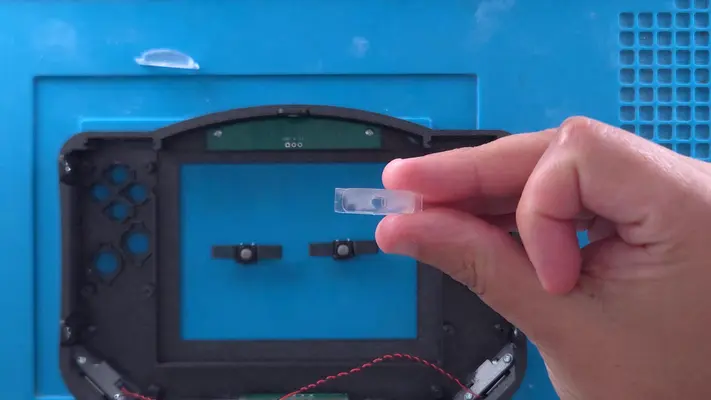
Preparing The Buttons & Button Pads
STEP SUMMARY
The process of SLA 3D Printing by its nature allows for some amazingly detailed surface finishes and mechanical tolerances. The downside is that it's a messy process but more than that, the process requires a great number of support structures which have to be removed. Though I have taken care of that part for you, the small burrs and bumps they leave behind will still be on them and have to be finished.
We will cover how to do that as well as prepare the B & A Buttons for the rubber membranes, as they are the only two that can't free-float like the others. SAFETY CHECK POINT PROTECTIVE GLOVES ARE HIGHLY RECOMMENDED
DIFFICULTY - EASY
TOOLS NEEDED
- 80 to 120 GRIT SAND PAPER OR NAIL FILE
MATERIALS NEEDED
- SUPER GLUE
PARTS NEEDED
- QTY (ALL REMAINING) - BAG #5 WILL BE NEEDED
STEP PROCESS
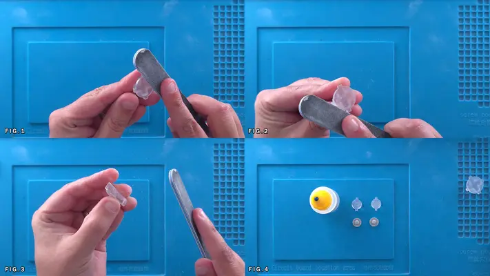
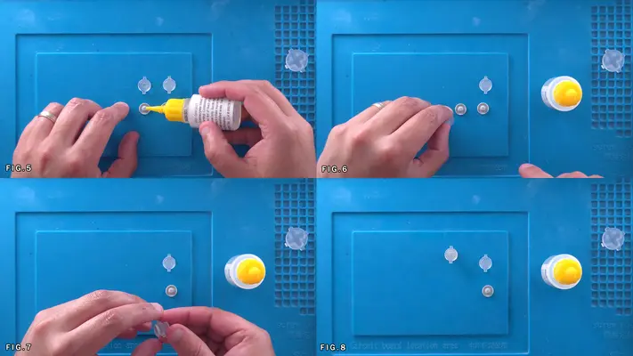
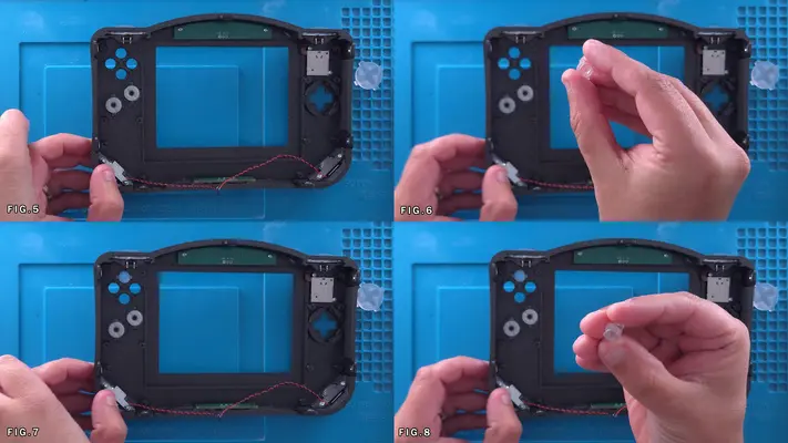
1. As we had to do already with the Power/Volume buttons and the R/L/Z, we have to clean up the D-Pad, C-Buttons and the B/A buttons.
2. Cleaning up the burrs is not overly difficult, but we do want to use cation so what we don't accidently scratch the visible surfaces of the buttons. This is why I prefer the use of Nail Files as they add a lot more control than standard sheets of sand paper.
3. Starting with the D-Pad, sand all the burrs of the bottom and along all the edges, making sure it's clean as possible. 4. Repeat the same process with the rest of the buttons, including with the Z-buttons if haven't already.
5. After this is complete, gather the A & B buttons and the two single button membranes and Super Glue. Fig.4
6. Place a very small dab of Super Glue on the tip of one of the single button membranes as shown in Fig. 5 and then place either the A or B button lightly on top. You will notice there is a center recess in the buttons for this very purpose.
7. Once again, the clock is ticking and we need to make sure the membrane and button are as centered to each other as possible. After it looks good and there is no visible glue outside where it was applied, push down on the button a few times to test if it pops back up like it should.
8. Repeat this process for the other button.
PROCEED TO NEXT STEP
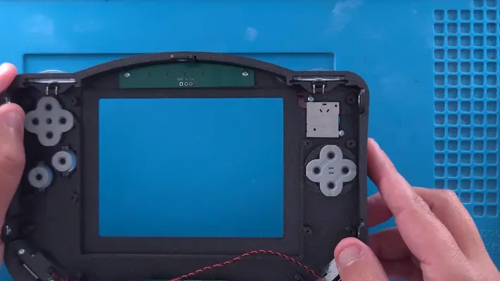
Installing The Buttons & Pads
STEP SUMMARY
Once the buttons have been prepped and cleaned up, placing them is next. This is an easy step, but we do have to be careful about button orientation, as it is a bit frustrating to get the buttons in place, put everything else in, only to realize things are backwards!
DIFFICULTY - EASY
TOOLS NEEDED
- NONE
MATERIALS NEEDED
- NONE
PARTS NEEDED
- PREPPED BUTTONS AND MEMBRANES
STEP PROCESS
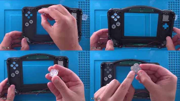
1. I generally start on the left side with the B button and work my way over. As mentioned before, double check your orientation and what button you actually have in your hand. Fig.2&3
2. Grab the A button and repeat the process. Fig.4&5
3. Moving on to the C buttons you will notice there are two variants. -^- and -<- 4. -^- are for the C-up and C-down and -<- are for C-Left and C-Right. Just keep a sharp eye as off all the button on this Front Face, those are the easiest to screw up. Fig.6-10
5. After the C buttons are placed, move on to the D-Pad. The D-Pad doesn't matter which way it goes in. Fig. 11
6. Placing the membranes is the next step and it does matter which one you use where. Grab the one with the hole in the center as shown in Fig. 12
7. This is for the C-Buttons and you will notice the case has an alignment pin built in for that. The pad should fit nicely over all the C-buttons and should not rotate.
8. Find the membrane that looks similar with the two lines in the center and place that over the D-pad. The membrane should fit inside built-in mounting bracket. PROCEED TO NEXT STEP

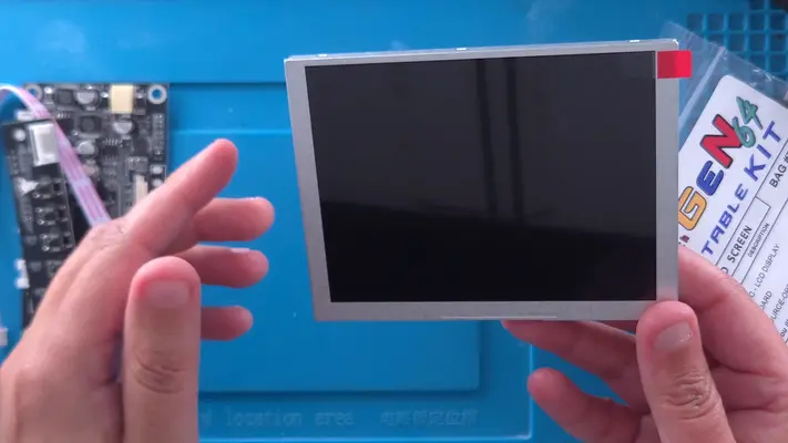
Installing The Display
STEP SUMMARY
In this step we will be installing the display for the system.
DIFFICULTY - EASY
TOOLS NEEDED
- NONE
MATERIALS NEEDED
- NONE
PARTS NEEDED
- QTY (1) - BAG #7 - ZJ050NA-08C LCD DISPLAY
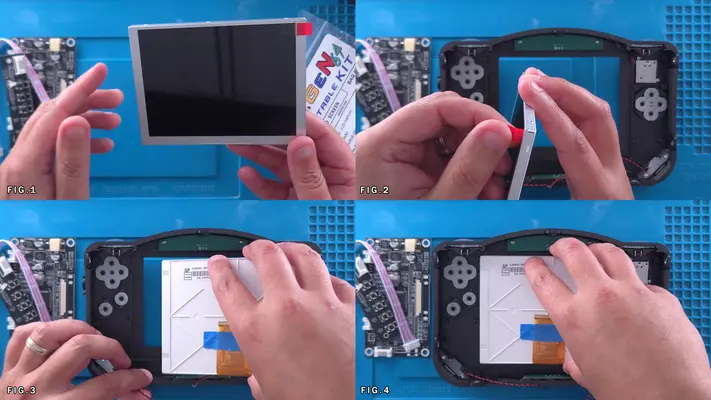
STEP PROCESS
1. Peel forward the screen protector tab so it sits at 90ish degree angle. This will help with its removal after it's been installed into the case. Fig.2
2. Slide the screen in from right to left to make sure the tab doesn't get buried behind the case, making it difficult to peel off after.
3. We will firmly secure the display in place in a later step.
PROCEED TO NEXT STEP
Installing The Main Motherboard & Joy Con
STEP SUMMARY
This is where everything really feels like it's coming together and while the process itself is easy enough, this get's a Moderate difficulty rating simply because of how much a pain in the butt the Joy Con cable is to install.
Also please note that the main motherboard shown in the this step is about 2 versions behind what will be shipping in the kit. While this doesn't have any effect on the end product, you will see a few extra holes in the board that aren't there anymore and the color of course!
DIFFICULTY - MODERATE
TOOLS NEEDED
- P1 PHILLIPS SCREWDRIVER
- PRECISION FLATHEAD SCREWDRIVER - TWEEZERS - NEEDLE NOSE PLIERS
MATERIALS NEEDED
- NONE
PARTS NEEDED
- FRONT FACE ASSEMBLY - POPULATED
- 5TH GEN64 MAIN MOTHERBOARD - POPULATED
- QTY (12) - BAG #1/D or H - #1 X 3/16" PPHMS
STEP PROCESS
1. Feed the Main Motherboard into the base of the Front Face Assembly, using the headphone jack to align the board. Fig.1
2. You'll find that the edge of the motherboard rubs up against side Mounting Brackets. You will have to slightly push them back while pressing down on the PCB.
3. Once we're past the bracket, before we can screw the PCB down, we need to feed the ribbon cable of the Joy Con through the slot on the PCB. There is VERY LITTLE slack to work with and you can easily damage the ribbon if you're not careful, so take your time with this.
4. As shown through Fig. 2-5, lift the main PCB up and locate the ribbon cable. Using a pair of tweezers, carefully fish the cable through the slot. This is easier said than done.
5. Once the cable has made it through the slot (Fig.5), carefully check to make sure none of the button membranes have been knocked out of place or are uneven.
6. If all looks clear, press the board down flat against the standoffs.
7. The next "FUN" part is feeding the end of the Joy Con Ribbon Cable into the connector on the board. Using the Flathead screwdriver, lift the latch on the connector as shown in Fig. 6-7 (hahaha)
8. I find using Needle Nose Pliers work best for grabbing the hard part of the cable on the edges and feeding it into the connector. Fig.8
9. Once the cable is in the connector, close it down with your finger or screwdriver. Fig. 10&11
10. Next we need to secure the board in place using the 12 mounting holes and #1 screws. Fig. 11-16
11. After the screws have been placed, double check to make sure they weren't too tight and that all the buttons still press nicely and are not tight. If so, back off the screws next to the buttons that are tight, just a quarter turn at a time. You can really dial in your preferred button travel this way as well. PROCEED TO NEXT STEP
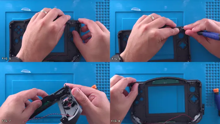
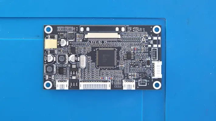
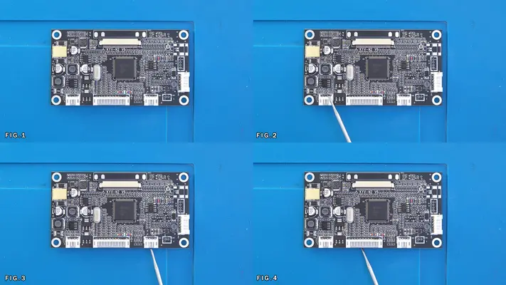
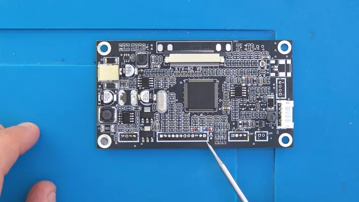
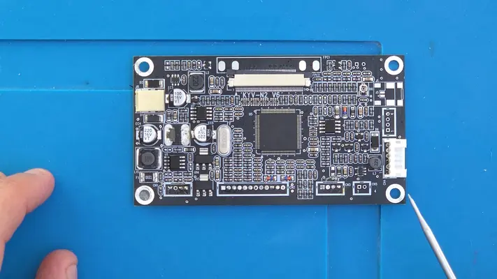
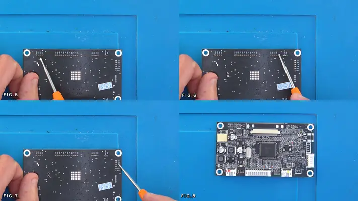
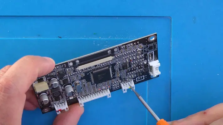
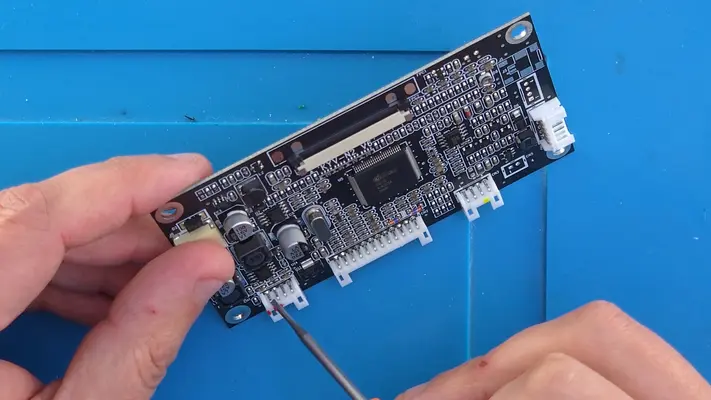
Preparing The LCD Driver Board
STEP SUMMARY
This is an optional step where if you prefer, you can remove the VGA, Power and Video connectors. The only real reason you might want to do this is the ease of wiring directly to the pin vias instead of the pins themselves and that the board will sit flatter on the back of the screen. Again though, it is not required and there is plenty of room in case to not to not have to worry about space. NOTE: You will notice that the rest of the steps in this section shows that the connectors were removed, but again, it was personal preference.
DIFFICULTY - EASY
TOOLS NEEDED
- CUTTERS
- PRECISION FLAT HEAD SCREWDRIVER
MATERIALS NEEDED
- NONE
PARTS NEEDED
- QTY(1) - BAG #7 - DRIVER BOARD
STEP PROCESS
1. If you plan to remove the connectors, note that we can only take off the Power Connector (Fig.2), the Video Connector (Fig.3) and the VGA Connector (Fig.4) The screens button board connector needs to stay intact as if you plan to make any screen adjustments or have to change the input, you will need it.
2. You can remove these in anyway you wish, like de-soldering braid or pump, or you can just chop it up with cutters and then remove the pins. Just as long as you're careful not to damage any components on the board.
3. Fig. 5-7 shows the silk screen and the which pins are what.
4. If you plan to leave the board as is, you will have to wire to the pins directly in later steps. Fig. 8 and the pictures after it show the points we'll need to wire too when the time comes.
5. Though you won't need to do this step until later as well, the final Figs show how to connect the button board cable.
PROCEED TO NEXT STEP
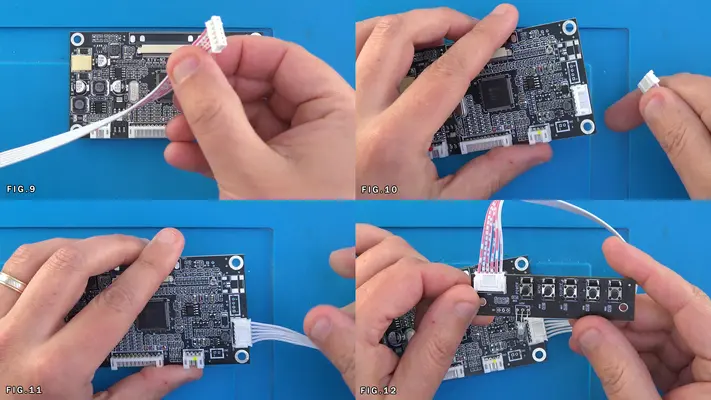
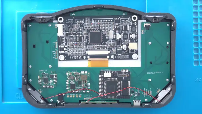
Installing The Display Driver Board
STEP SUMMARY
Installing the Driver Board represents the last component of the Front Face Assembly and is fortunately a very easy step to accomplish! Sorry the images are a little "overexposed" in the sections.
DIFFICULTY - EASY
TOOLS NEEDED
- PRECISION FLAT HEAD SCREWDRIVER
MATERIALS NEEDED
- GOOP - Q-TIPS
PARTS NEEDED
- QTY (1) - BAG #7 - LCD DRIVER BOARD
STEP PROCESS
1. Make sure the connector on the driver board is pulled forward so that it is open.
2. Feed the Ribbon cable from the display into the connector as shown in Fig.1
3. Making sure the cable is straight, use the precision screwdriver to close the connector by pushing in the tabs on either side. Fig. 2&3
4. Hit the 4 mounting holes on the driver board with a little bit of Goop and then pull back the board so the top edge is inline with the Main motherboard PCB.
PROCEED TO NEXT STEP
PART VII - WIRING THE FRONT FACE ASSEMBLY
- Wiring The R & L Buttons
- Connecting The LED Backlight
- Connecting Display Power
- Connecting Display Video
OVERALL DIFFICULTY - EASY
CRITICAL STEP AND/OR SAFETY NOTICE
Connecting The Speakers
STEP SUMMARY
A very simple wire-up to bring all that retro audio goodness to ear!
DIFFICULTY - EASY
TOOLS NEEDED
- SOLDERING IRON
MATERIALS NEEDED
- SOLDER
PARTS NEEDED
- FRONT FACE ASSEMBLY
STEP PROCESS
1. Each speaker has a red and black wire which should be coiled up a couple of times to help take out the slack, but can be uncoiled if you need to remove the motherboard later.
2. Tin the pads and end of each wire which is already stripped.
3. Wire the Red wires to the L+ / R+ pads respectively.
4. Wire the Black wires the the L- / R- pads respectively.
5. Tuck the coiled wires under the motherboard
PROCEED TO NEXT STEP
Wiring The R&L Buttons
STEP SUMMARY
Similar to the speakers, but we have to add the wires ourselves.
DIFFICULTY - EASY
TOOLS NEEDED
- SOLDERING IRON
- WIRE STRIPPERS
MATERIALS NEEDED
- 30 AWG TWISTED PAIR - W/B - ABOUT 6 INCHES
- FLUX
PARTS NEEDED
- FRONT FACE ASSEMBLY
STEP PROCESS
1. Use some Flux on the legs of the tact switches for the R&L buttons.
2. Tin the legs and the LT/RT/GND pads on the tact switches and motherboard.
3. Untwist about 1/2" worth of wire from either side of each pair of wire and strip off a small amount of sheathing on each wire.
4. Hit each wire end with Flux and tin them as well.
5. For the sake of keeping the wiring consistent, I make the left leg of the tact switch the "signal" line and the right leg the "GND". In this case, White on the left, Black on the right. Wire each set firmly to the tact switch.
6. Like with the speakers, coil up the extra wire, then proceed to wire to the pads. White to the LT and RT pads respectively, Black to the GND. PROCEED TO NEXT STEP
Connecting The LED Backlight
STEP SUMMARY
Another simple and quick connection but this time with a three wire twisted set.
DIFFICULTY - EASY
TOOLS NEEDED
- SOLDERING IRON
- WIRE STRIPPERS
MATERIALS NEEDED
- 30 AWG - TRIPLE TWISTED SET - B/W/O - ABOUT 6" LENGTH
- SOLDER
- FLUX
PARTS NEEDED
- FRONT FACE ASSEMBLY
STEP PROCESS
1. Like with the R/L buttons, untwist about 1/2" of wire from the twisted set, strip a small amount of sheathing from each lead, flux and then tin all 6 connections.
2. Flux and Tin the L+/A/GND pads on both the main motherboard and the LED board.
3. Connect the L+ on the MB to the L+ on the LED board with the Orange wire. Connect the A on the MB to the A on the LED board with the White wire.
Connect the GND on the MB to the GND on the LED board with the Black wire.
4. Route the wire up and out of the way to the left.
PROCEED TO NEXT STEP
Connecting Display Power and Video
STEP SUMMARY
As mentioned at the "Preparing The Driver Board" section, I had chosen to remove the connectors on the driver board. If you did not, the placement will still be the same, you'll just have to wire to the pins instead of the pads. Also, the board will not sit flat against the display which you'll have already noticed by now. Again, it should not cause a problem.
DIFFICULTY - EASY
TOOLS NEEDED
- SOLDERING IRON
- WIRE STRIPPERS
- PLIERS or TWEEZERS (OPTIONAL)
MATERIALS NEEDED
- 30 AWG TWISTED PAIR - Y/B - VIDEO/GND - ABOUT 4" LENGTH
- 30 AWG TRIPLE TWISTED - R/O/B - 5V DISPLAY PWR - ABOUT 6" LENGTH
PARTS NEEDED
- FRONT FACE ASSEMBLY
STEP PROCESS
1. Like before, unwind, strip, flux and tin the ends of all conductors.
2. Tin the Video, GND and 5V pads that are seen in Fig.2
3. Using pliers, twist and connect the Red and Orange wires together to make them essentially one wire.
4. Wire the pair to either (or both) of the 12V pads on the driver board as shown in Fig.2 The right two pads are 12V, the left 2 are GND Wire the GND wire to one of those two pads on the left.
NOTE: THE PINOUT IS PRINTED ON THE BACK OF THE PCB IF YOU NEED TO MAKE SURE YOU'RE WIRING TO THE CORRECT PLACE.
5. Wire the other end of the R/O wire to the 5V pad on the Main Motherboard. Fig.4
6. Now take the Y/B Twisted Pair and wire the Yellow to the second pin on the video connector as show in Fig. 6
7. These pins alternate GND/V1 GND/V2, so be careful not let them cross over. Wire the GND to the first pad/pin on the video connector.
8. Wire the other end of the Yellow wire to the Video pad on the Main Motherboard, and wire the GND to the same GND pad as the display power.
PROCEED TO NEXT STEP
Wiring The Power and Volume Buttons
STEP SUMMARY
A simple process, but if you're not used to working with 34AWG wire, it might be a bit tricky. Since you can't strip this wire normally, you have to first melt a bit of the "sheathing" off. To do this, simply put a dab of Solder on the tip of your soldering iron so it becomes a little molten ball and simply pass the end of the wire through it a couple of times. This will insure your actual solder joint doesn't have a bunch of non-conductive sheathing mixed in with it.
DIFFICULTY - EASY
TOOLS NEEDED
- SOLDERING IRON
- TWEEZERS
MATERIALS NEEDED
- 34AWG WIRE - (4) 1" LENGTHS
- FLUX
PARTS NEEDED
- FRONT FACE ASSEMBLY
STEP PROCESS
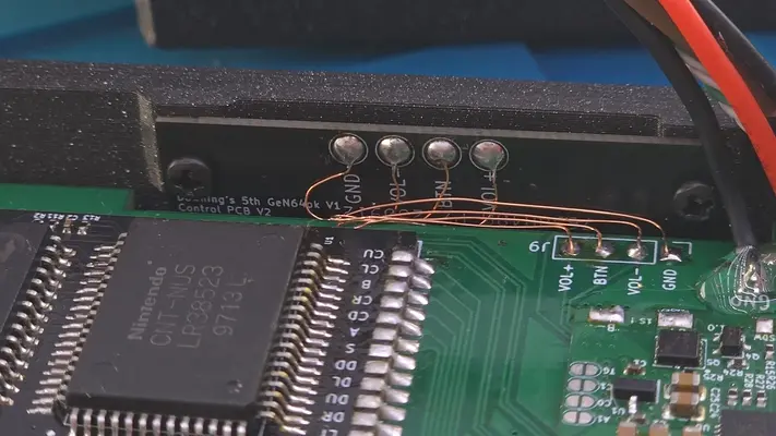
1. The goal here is to connect each solder pad with on the Main Motherboard with the Control PCB. Flux and Tin the pads on both.
2. Prepare the 1" strips of 34AWG with the solder ball method.
3. I will normally then solder all 4 onto the Main Motherboard, leaving them all standing straight up.
4. Using a pair of Tweezers, I'll then wire the GND wire to the GND pad on the control board. Then take up what slack is left and tuck it down between the and Main Motherboard.
5. Repeat this step with Vol-, BTN and Vol+. Doing it that order will keep the wires out of the way of each other as you're going.
6. Make sure your connections are tight and the wire is routed cleanly under the board. PROCEED TO NEXT STEP
PART VIII - THE BACK FACE ASSEMBLY
- Installing The Z Buttons
- Installing The Fan
OVERALL DIFFICULTY - MODERATE
CRITICAL STEP AND/OR SAFETY NOTICE

Mounting Internal Back Face Batteries - Part 1
STEP SUMMARY
This is one of the more complex assembly process' of the project with the most parts used at once vs any other step thus far. Fortunately, though the steps are many, their implementation is pretty easy as long as we break it down into small steps. Remember to TAKE YOUR TIME with all these steps involving batteries. Even I check myself every time I build one of these when it comes to these steps!
DIFFICULTY - MODERATE
TOOLS NEEDED
- NEEDLE NOSE PLIERS
- P2 PHILLIPS SCREW DRIVER- P1 PHILLIPS SCREW DRIVER
MATERIALS NEEDED
- NONE
PARTS NEEDED
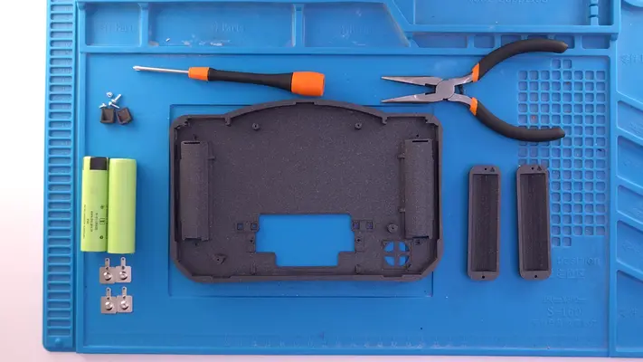
- Qty (2) 18650 3300mAh Battery Cells (Not Included)
- Qty (4) Bag #6 - 5223 Keystone Battery Clips- Qty (2) Bag #3/F - Battery Terminal Wedge
- Qty (2) Bag #1/C - LPP0204 Screws
- Qty (2) Battery Cover - 3D Printed
- Qty (2) Bag #1/D or H - #1 x 3/16 Screw
- Qty (1) Back Face Assembly
STEP PROCESS
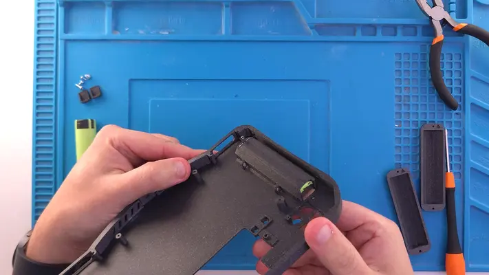
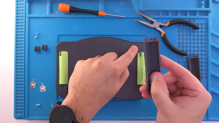
1. Make sure you have all the required parts and tools ready to go ahead of time as this will make the assembly a lot easier due to how many parts we're actually working with. Fig 1-6 shows each part we will be needing while Fig. 6&7 shows the battery covers and points out the arrow that is printed on it. This will be important later on.
2. Locate the two battery slots from the back of the case.
3. Grab one of the Battery Terminals, flip it so the terminal tab is facing down and that the ball is facing in as seen in Fig. 10-12 and insert the Tab into the slot.
4. Holding the Tab from the back as shown in Fig.13, insert one of the batteries with the + side facing up! Fig. 14-16
5. Flip to the inside of the case and make sure the tab is level with the top of the batter compartment as shown in the image after Fig.16
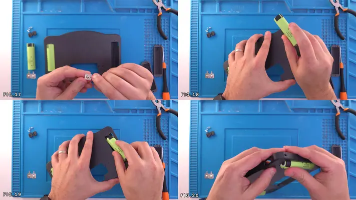
6. Repeat this step for the other side. The batteries will go in tight which is what we want and should be press-fit in place so when you pick it up, you should not have to hold them in place. Fig. 17-20 and the pic right after.
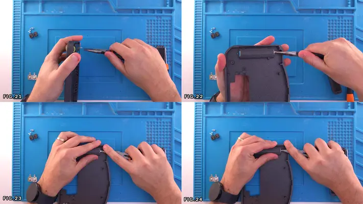
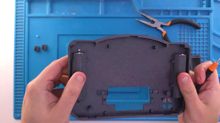
7. Next, using a pair of Needle Nose Pliers we need to bend the tabs over around the back of the battery compartment. Start straight up from the top and bend at a 90 degree angle. Fig. 21-22
8. Using the wide-edge of your pliers and your finger, apply downward pressure so the bend starts to flatten out and evenly bend over the back of the battery compartment. Fig. 23
9. Once there is enough of a bend, carefully using the tip of the pliers, push in tabs so it sits as flat as possible to the back of the battery compartment as shown in Fig. 24 and additional pictures.
10. Repeat this for the other side. Note that this is fairly tricky to pull off cleanly, but realistically, as long as the tab isn't sticking straight up, it won't affect the rest of the build, so don't sweat it if it isn't perfect!
PROCEED TO PART 2 of THIS STEP
Mounting Internal Back Face Batteries - Part 2
STEP SUMMARY
In this step we'll be mounting the battery covers as well as the bottom battery terminals. Again this is kind of a more complex part of the build, but again, baby steps make it pretty easy. All the same tools, materials and parts from the last step apply.
STEP PROCESS
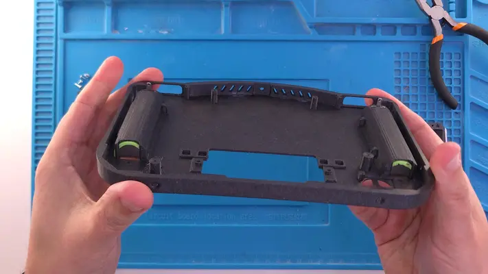
1. Grab one of the battery covers and locate the arrow that has been printed into it. Make sure this arrow faces the toward the top of the case as shown in the first two images, as the mounting holes are slightly different sizes.
2. Take one of the #1 x 3/16" Sheet Metal Screws and feed it through the top screw hole as shown in Fig. 1&2
3. Place the Battery Cover over the Battery on the back and find the mounting hole with the screw that was pushed through. Fig. 3-6
4. Once it's lined up, using the P1 Phillips, tighten the screw so the battery cover sits flat. Fig. 7-8 and the following image.
5. Repeat for the other side.
6. Next, grab one of the Battery Terminal Wedges and one LPP0204 Thread Forming Screw. Place the screw into the Wedge as show in Fig. 11
7. With the P2 Phillips Driver, screw the Wedge in place at the base of the battery with the flat side facing it. Make sure the screw starts to thread into the Battery Cover correctly, but DO NOT TIGHTEN FULLY. Fig. 12 and following image.
8. Repeat this for the other side.
9. Next take one of the Battery Terminals and like last time, make sure the domed end is face toward the battery.
10. Place the Battery Terminal between the Battery and the Wedge and then fully tighten the Wedge. You will probably have to hold the Wedge from spinning while you tighten and also holding the terminal. It can be a bit tricky, but in the end, the terminal should appear as shown in Fig. 17-19
11. Using the same technique as the last section, bend the terminal tabs down over the Wedge, being a little more careful though as the Wedge can move under pressure.
PROCEED TO NEXT STEP
Mounting The Square Nuts to Back Face Plate
STEP SUMMARY
The next step to secure the 4 square nuts into the traps for the Cart Slot Mounts.
DIFFICULTY - EASY
TOOLS NEEDED
- NONE
MATERIALS NEEDED
- GOOP
- Q-TIP
PARTS NEEDED
- QTY (4) - BAG #1/G - #2-56 SQ NUT
STEP PROCESS
1. Layout the 4 Square Nuts.
2. Using a Q-tip or some other kind of spreader, put a small amount of Goop in each nut trap as shown in Fig. 4-6
3. Place one nut in each trap, making sure the Goop has a firm bond around it.
4. Use a Q-Tip to then clean out the thread and the screw holes as much as possible.
5. After the Goop dries, take one of the #2-56 machine screws and thread it through the nut and screw holes on the case a couple of times to make sure the threads are clean.
PROCEED TO NEXT STEP
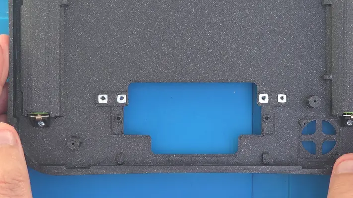
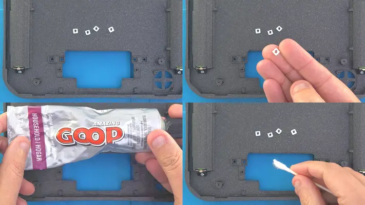
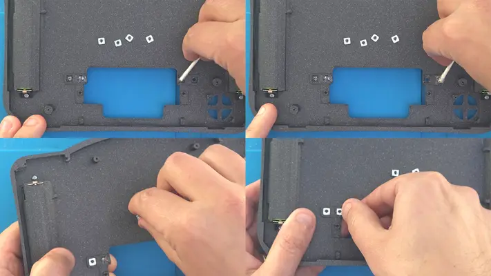
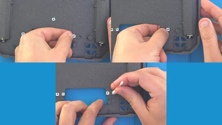
Installing The Z Buttons
STEP SUMMARY
This is the same exact process as the R&L buttons and you should already have the buttons and tact switch assemblies all ready to go.
DIFFICULTY - EASY
TOOLS NEEDED
- PRECISION FLAT HEAD SCREW DRIVER
MATERIALS NEEDED
- GOOP
- Q-TIP
PARTS NEEDED
- QTY (2) - BAG #5/D - Z BUTTON - SLA 3D PRINTED
- BACK FACE ASSEMBLY
STEP PROCESS
1. Refer back to "Installing The R&L Buttons" Step from The Front Face Assembly.
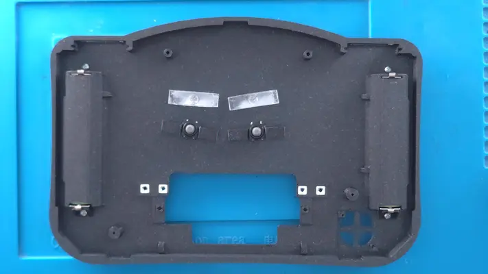
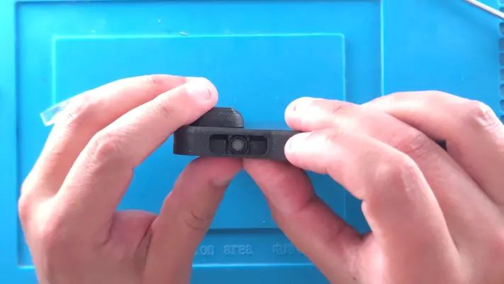
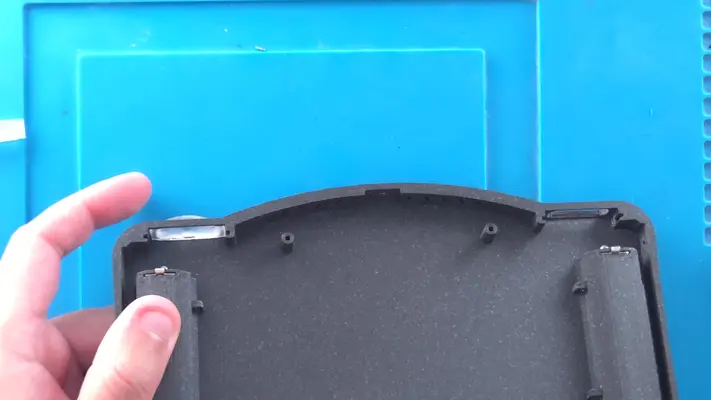
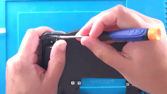
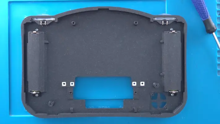
Mounting The Blower Fan
STEP SUMMARY
Another simple step is mounting the blower fan to help keep the system cool. 2 screws and we're done!
DIFFICULTY - EASY
TOOLS NEEDED
- P1 PHILLIPS SCREW DRIVER
MATERIALS NEEDED
- NONE
PARTS NEEDED
- QTY (1) - BAG #6 - 5V BLOWER FAN
- QTY (2) - BAG #1/D or H - #1 X 3/16" PPHSMS
STEP PROCESS
1. Blower fans are a bit different than conventional cooling fans as these take in air from the face, but blow the air out the side. It won't seem like much when the case is open, but when it's closed up, it moves a fair amount of air through the unit.
2. Align the fan so the open end is pointing left towards the interior of the enclosure and the back of the fan is facing us.
3. Gently screw the fan to the standoffs as shown.
4. When complete, snip the connector and coil up the wire for now.
PROCEED TO NEXT STEP
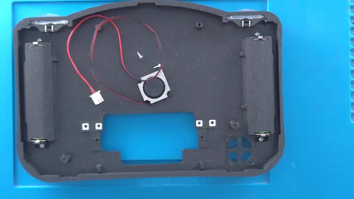
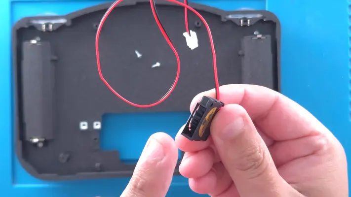
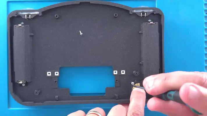
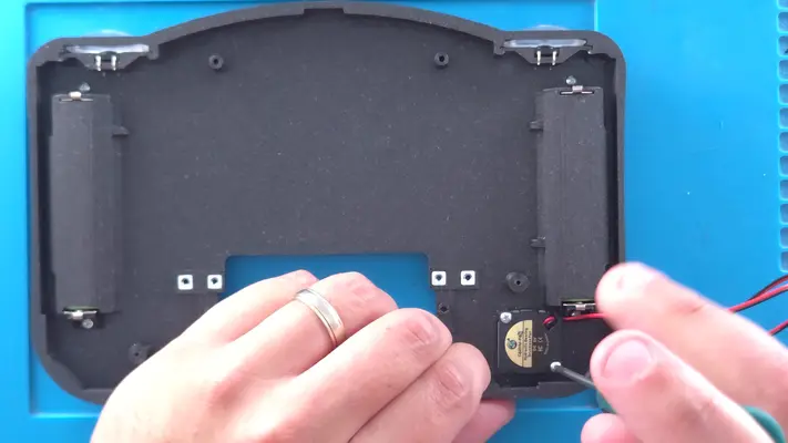
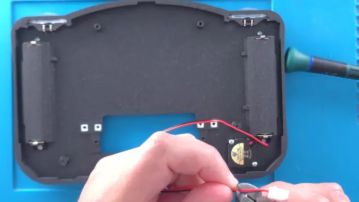
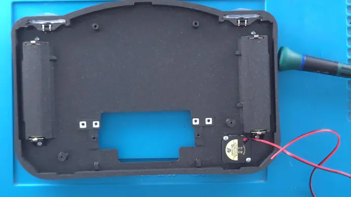
Mounting Reset Switch to Cart Cover
STEP SUMMARY
Although this is a fairly easy step on its own, there are a couple of different methods I've been playing around with both have about the same amount of success.
DIFFICULTY - EASY
TOOLS NEEDED
- P1 PHILLIPS SCREW DRIVER
MATERIALS NEEDED
- GOOP (OPTIONAL)
- Q-TIP (OPTIONAL)
PARTS NEEDED
- Qty (1) Cart Cover - 3D Printed
- Qty (1) Bag #6 - 6x6x5mm Tact Switch- Qty (1) Bag #6/Spares Bag - #2-56 x 1/8" PHMS BLK Oxide Screw (OPTIONAL)
STEP PROCESS
Again, both work, but I feel that the glue method ends up working out a bit better in the long run.
PROCEED TO NEXT STEP
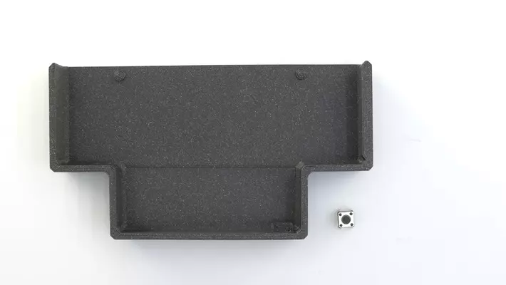
PART IX - WIRING THE BACKFACE ASSEMBLY
SECTION SUMMARY
This will be the sequence of steps that is by far the easiest to catastrophically mess something up, so please be sure to READ every part of this section!
OVERALL DIFFICULTY - MODERATE
CRITICAL STEP AND/OR SAFETY NOTICE
BACK TO TABLE OF CONTENTS

Wiring The Z Buttons
STEP SUMMARY
This step is a simple repeat of the R&L Button wiring step but with a different color wire but in this case, we won't be wiring to the Main PCB just yet.
DIFFICULTY - EASY
TOOLS NEEDED
- SOLDERING IRON
- CUTTERS - FLAT NOSE PLIERS
MATERIALS NEEDED
- FLUX
- SOLDER
- 30AWG - TWISTED PAIR - G/B -2 LENGTHS ABOUT 8" EACH
PARTS NEEDED
- BACK FACE ASSEMBLY
STEP PROCESS
1. As before, using the Flux, hit the legs of the tact switches and the stripped leads of the wire and then Tin them all. Fig. 1-4
2. This time however, start with the Z button on the right and solder the wire to the legs, again with the color on the left and black on the right. Fig. 5&6
3. Measure out a length that will get your right to the center of the Z button on the left, routing the wire loosely up by the curve of the case. Cut to length. Fig. 7&8
4. With your other length of wire, untwist about 1/2" and strip about 1/4" of sheathing off the Black and Green. Do the same with the other end of the wire you just Soldered to the other switch.
5. Twist the colored pairs together with the Flat Nose Pliers as shown in Fig. 9-13
6. Flux and Tin the wires and then solder them to the tact switch as shown in Fig. 14&15
7. Feed the loose part of the cable through the cable management ring. PROCEED TO NEXT STEP
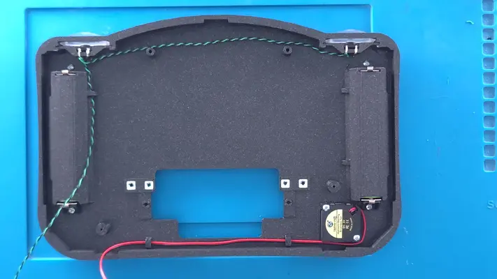
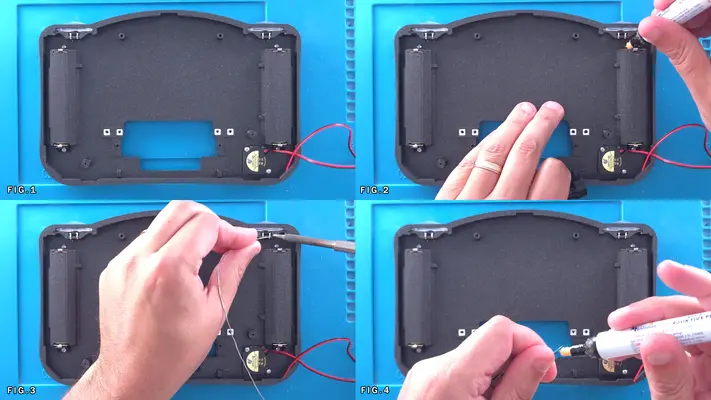
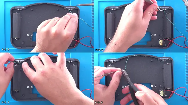
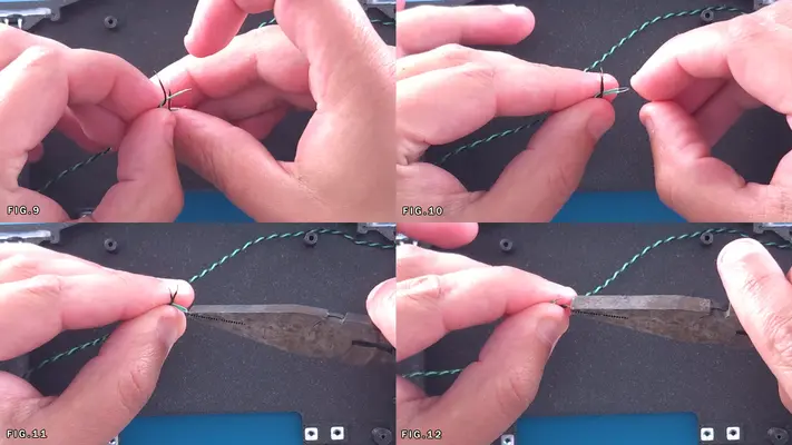
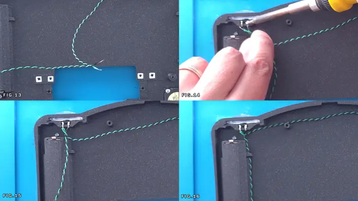
Wiring The Positive Battery Power
STEP SUMMARY
In this step we will be wiring up the two 18650 Batteries in Parallel with each other and prepping for attachment to the Main Mother Board. Fairly straightforward wiring like the last step, however remember that you will be working with live wires from here out.
DIFFICULTY - EASY
TOOLS NEEDED
- SOLDERING IRON
- WIRE STRIPPERS
MATERIALS NEEDED
- SOLDER
- FLUX
- 22AWG WIRE - RED - 2 LENGTHS APPROX 10" INCHES
PARTS NEEDED
- BACKFACE ASSEMBLY
STEP PROCESS
1. Flux and Tin all 4 Battery Terminals as shown in Fig. 1-4
2. Strip a small amount of sheathing off the wire (1/4" max) and then Tin the wire.
3. Slightly bend the "Tinned" part of the wire so it's around a 90 degree angle to the sheathing.
4. With the wire facing up and too the left (Fig.6), solder it too the Battery terminal on the Top (+ Side) of the Right Battery.
5. Rotate the Assembly so that Solder point is right in front of you and you can make sure that it is secure and as flat against the terminal as possible and does not go above the battery holder. You can use pliers if need be to make sure is secure. Fig 7&8
6. Feed the wire up around the top like you did with the Z button wire and measure to the Battery terminal on the other side, leaving just a little extra for bending and twisting in the next steps, then cut. Fig. 10
7. Strip off about a 1/4" of sheathing off that wire and the other length and twist the bare wire together to make a single joint and then Tin it. Fig. 11-14
8. Like we did with the other side, bend the pair of wires at a 90 degree angle, face it up and solder to the battery terminal, again as close to the battery holder as possible. Fig. 15&16
9. Take the loose end and feed it though the cable holder like we did with the Z button cable. PROCEED TO NEXT STEP
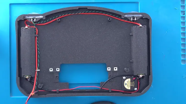
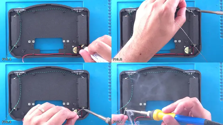
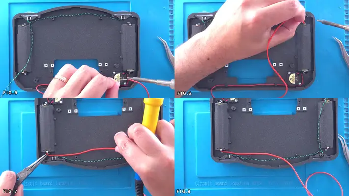
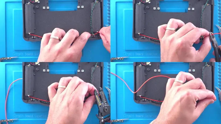
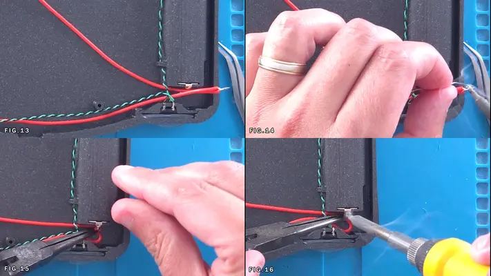
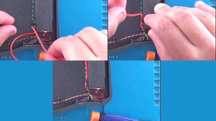
Wiring The Negative Battery Power & Fan Wiring
STEP SUMMARY
In this step, not only will we be wiring up the Negative Battery Power, but we also need to partially wire up the Fan at the same time as it will share a ground connection and will need will need to be routed with the main ground line. The wiring here can be a bit tricky as we're trying to add multiple wires to a single spot, but in doing so, we cut out a lot of extra wire that would just be taking up space in the case otherwise.
DIFFICULTY - MODERATE
TOOLS NEEDED
- SOLDERING IRON
- NEEDLE NOSE PLIERS or TWEEZERS - WIRE STRIPPERS
MATERIALS NEEDED
- 22AWG WIRE - BLACK - 2 LENGTHS APROX 10" INCHES
- SOLDER
PARTS NEEDED
- BACK FACE ASSEMBLY
STEP PROCESS
1. Like last time, start with the right battery, Strip, Tin, Bend and solder a length of 22AWG Black wire into place. Fig. 1-3
2. Locate the wires that go to the fan. There should be a Red and Black wire that attached to each other. Locate the ends where you cut the connector off earlier and using a knife, gently press between the two wires (no more than a 1/4" total length of cut) to separate the two, then gently peel the wires apart right down to the fan itself. Fig. 3&4
3. Move the Red fan wire out of the way for the time being and cut the Black fan wire down to about 2" inches in length, then strip about a 1/4" of sheathing off it, Tin and solder to the same Battery terminal. Fig. 5-8
4. Next take the Red Fan wire and the 22AWG Black that is soldered to the terminal and route it down the front of the case using the built in cable holders. They may fit tight depending on the wire you chose, so if it's too tight, you don't have to use the holders. A few dabs of hot glue or Goop will suffice. Fig. 9-11
5. Grab the other length of 22AWG Black wire and with Black wire we just brought over from the Right battery, strip and twist together, Tin and bend like we did with the Red wires in the previous step.
6. Solder these wires to the Bottom Left Battery Terminal and run the line down with the Red and z button wires. Fig. 12-14
7. Next, cut about a 2" strip of 22AWG Black wire, Strip/Tin/Bend like before and solder to the Bottom Right Battery Terminal along with the Fan GND and the first GND wire we soldered to it. Fig. 16 This will be used in the next step.
PROCEED TO NEXT STEP
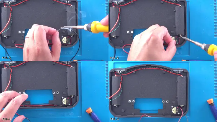
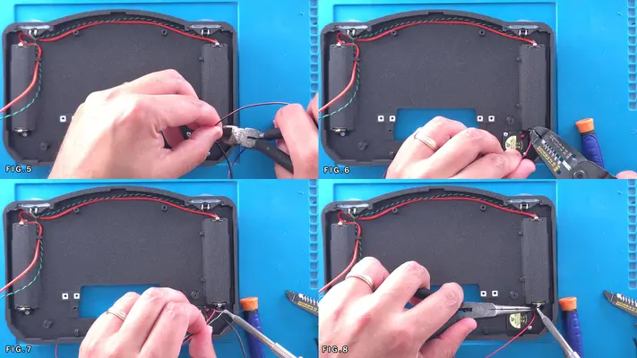
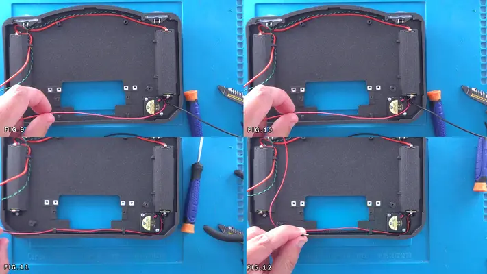
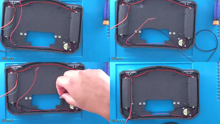
Wiring The Batteries - Part 3 - Test & Clean Up
STEP SUMMARY
The last step of this process is a double check to make sure the batteries have been installed and wired up correctly, as well as tidy up the loose wires and cover up some solder joints.
DIFFICULTY - EASY
TOOLS NEEDED
- DIGITAL MULTIMETER
MATERIALS NEEDED
- ELECTRICAL TAPE
PARTS NEEDED
- BACK FACE ASSEMBLY
STEP PROCESS
1. The most important part here is to test to make sure the batteries have been wired in Parallel correctly. With you Multimeter set to DC, put the Red lead to the (+) side of the right battery and the Black lead to the (-) side of the battery. You should get a reading between 3.5V to 4.2V
2. Repeat for the other side and you should get the same.
3. IF you get a -3.5V to -4.2V reading, it means you've put both cells in upside down and will need take the battery covers off and flip the cells.
IF you get a - or +7.4V, it means you've flipped one cell and have wired the batteries in Series instead of Parallel, in which case you'll have to do the same thing, pop the covers and figure out which cell is upside down.
This will be very rare this happens though as long as you followed the steps correctly when you first put the batteries in.
4. Once confirmed the Batteries are in correctly, we then need to cover up the Battery Terminals and solder joints as a precaution. In theory they shouldn't contact anything in the case once put together, but since we still have a few steps where things are actively going to be moved around, it will be good to keep them covered just in case. With some electrical tape, see Figs. 4-8
PROCEED TO NEXT STEP
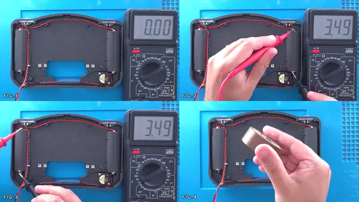
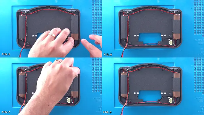
Mounting & Installing The 3rd 18650 Battery
STEP SUMMARY
While installing this assembly isn't overly difficult, we need to be cautious and act as though everything now has voltage going to it. While it's not likely going to cause any problems because we don't have any of the sensitive electronics hooked up yet, we don't accidently want to contact anything that might get a jolt out of it, yourself included!
UPDATE - These steps have been slightly modified from the original guide to help mitigate the risk of potential hazards while working with live contacts. See below.
DIFFICULTY - EASY
TOOLS NEEDED
- SOLDERING IRON
- P2 PHILLIPS SCREW DRIVER
- WIRE STRIPPERS
MATERIALS NEEDED
- SOLDER
PARTS NEEDED
- BACK FACE ASSEMBLY
- 3RD BATTERY PCB ASSEMBLY
- QTY (2) - BAG #1/F - #2-56 X 1/8" PPHMS BLK
STEP PROCESS
1. Orient the PCB Assembly as seen in Fig. 1 and then place over the mounting posts as seen in Fig. 2&3.
NOTE: You will notice that the posts in this case are "internal", which means they fit through the PCB, not below it. You will also notice they are split and hallow. This is because this is an expansion style mounting system, whereas when the screw is tightened, it puts pressure on the side walls and holes the PCB in place. However due to 3D printing variances, it might not have quiet enough bite to it, which means when it's time to hold it in place permanently, we may have go a bit old school, but we'll cover that when we get there.
2. Using the 2 screws, mount the Assembly in place, but if you find it's not being gripped well enough by the screws, don't put any glue on them as of yet. we're going to have to move things around again shortly to get the cart slot through.
NOTE: You may have to raise the whole case off the mat because of the battery brackets on the PCB assembly. They tend to not make it want to sit flat and can make assembly more difficult.
UPDATE - NEW RECOMMEND PROCEDURE - RESOLUTION TO ISSUE I2
We're going to sort of change up the procedure here as feedback from those who have been putting the kits together has been consistent in that wiring the 3rd battery bracket and having the clips be live is a potential hazard with one N64 motherboard already getting toasted. So the steps and the Figures are going to be slightly different.
3. Next as shown in Fig.8, measure the short ground wire that connects with the battery (-) and fan (-) to the (-) through hole on the 3rd Battery PCB.
4. Cut to length, tin the wire and then solder the wire to the (-) solder point. Fig. 9&10
5. Repeat the process of Step 3 with the positive (Red) battery line, HOWEVER, DO NOT wire this up to the 3rd Battery assembly just yet. I understand Fig. 11-15 show this, but as soon as this is connected, the contacts are live, which unless are covered in some method, opens up the potential for shorts and damage. Again, I've never had an issue but it is easy to overlook.
6. You can however cut about an 8" inch length of 22AWG Red and connect that to one of the (+) solder points on the 3rd Battery PCB and feed it down with the rest of the wires as shown in Fig.16
7. This will get us as close to ready as possible without actually having any live contacts exposed until after the Cartridge Slot is mounted. We will connect the live battery power lead at that point.
BACK TO TABLE OF CONTENTS
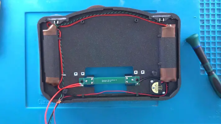
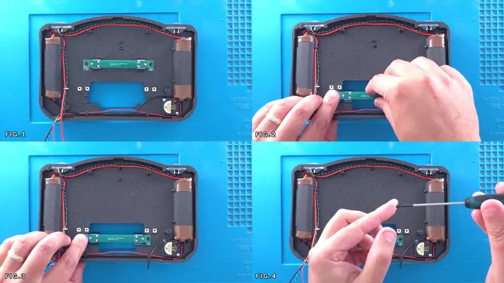
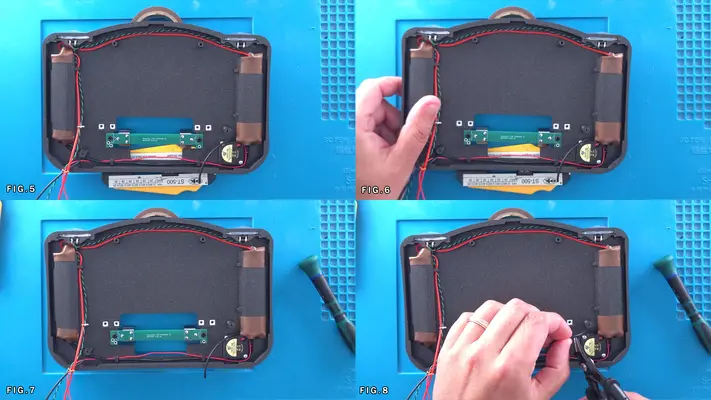
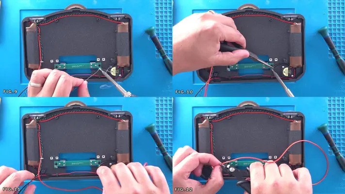
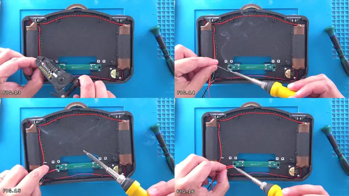
PART X - MOUNTING THE N64 & CART SLOT
SECTION SUMMARY
OVERALL DIFFICULTY - MODERATE
CRITICAL STEP AND/OR SAFETY NOTICE
1. KEEP AN EYE OUT ON THE LIVE CONNECTIONS AND/OR CONNECTORS

Preparing The Cart Slot Brackets
STEP SUMMARY
The Cart Slot Brackets are what hold the Stiffener to the Back Face Plate as well as what the Cart Cover mount too. But first we need to get the hardware mounted to the brackets themselves.
DIFFICULTY - EASY
TOOLS NEEDED
- NEEDLE NOSE PLIERS
- P2 PHILLIPS SCREW DRIVER
MATERIALS NEEDED
- GOOP
PARTS NEEDED
- QTY (2) - BAG #1/G - #2-56 SQ NUTS
- QTY (4) - BAG #1/A - #2-56 X 5/8 PPHMS
- QTY (2) - BAG #3/D - CART SLOT MOUNTING BRACKETS
STEP PROCESS
1. Using pliers, remove the support material from both Mounting Brackets. Fig 1-3
2. Test fit a Square Nut into the trap. If it fits nice an tight and flush, leave as is. - If slightly too tight, but you think it will fit, take one of the screws and tighten the nut until it sets into place. Fig 4-6 - If too loose, place some Goop in the trap, place the nut and clean the threads like we did with the case mounting brackets. Fig. 7&8
3. As Fig. 9 shows, align the brackets so the the screws are on the bottom and the nut trap is on the top. (You will have to flip either one of them to make this work.)
4. Now insert the screws into the 4 screw holes, leaving them as shown in the last image in this step. (They will fit tight, so you may have to use a screw driver to screw them in place.)
PROCEED TO NEXT STEP
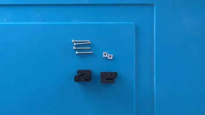
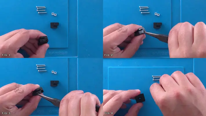
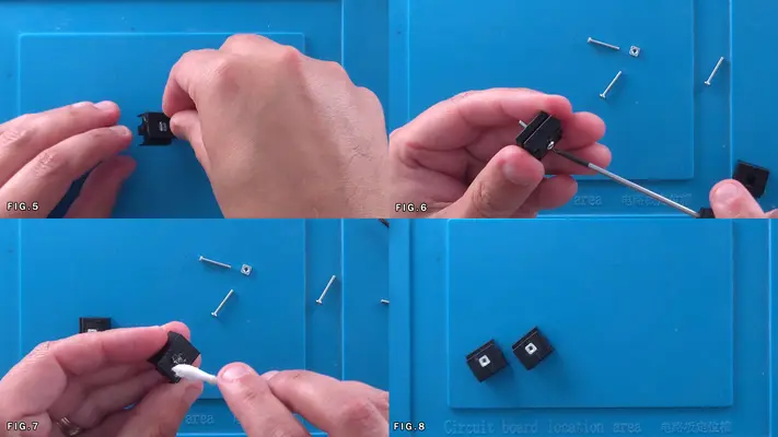
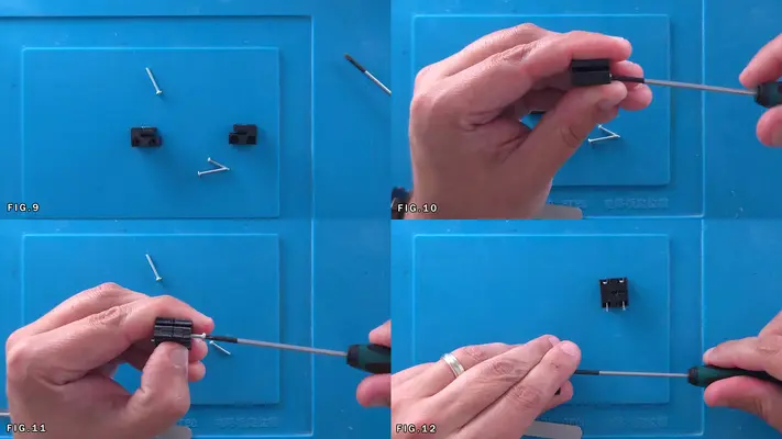
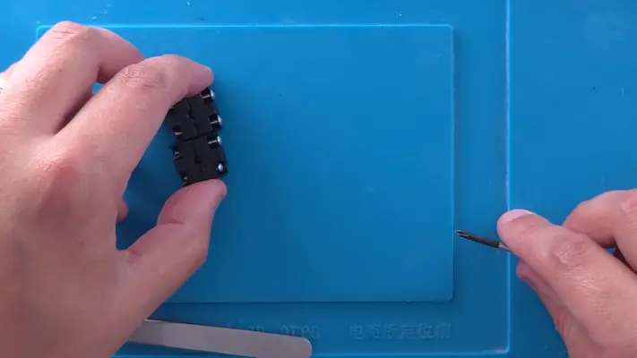
Mounting the N64 To The Back Face Assembly
STEP SUMMARY
This step is a bit tricky due having to navigate around live connections and carefully feeding the Cart Slot through to the back of the unit.
DIFFICULTY - MODERATE
TOOLS NEEDED
- P2 PHILLIPS SCREW DRIVER
MATERIALS NEEDED
- ELECTRICAL TAPE (OPTIONAL)
PARTS NEEDED
- BACKFACE ASSEMBLY
- N64 MOTHERBOARD ASSEMBLY
- QTY (3) - BAG #1/D OR H - #1 X 3/16" SCREW
STEP PROCESS
1. First we need to move the 3rd battery holder out of the way. Unscrew the board and carefully pull it toward the front as seen in Fig. 1
NOTE: REMEMBER - The two battery terminals are still live even without the 3rd battery in it. If it makes you more comfortable, you can take the other two batteries out and put them back in after, though it will be a bit of a process to do so. Or, you can take a bit of electrical tape and temporarily cover the terminals...or do like I do and just freaking send it!
2. Carefully take the N64 and while supporting the cart slot, turn it over so that the top of the N64 Mobo is face down toward the Back Face Plate and gently feed the cart slot through the back as seen in Fig. 3&4
3. Once through, carefully flip the N64 up and over as seen in Fig. 5&6
4. Fasten the 3rd Battery Mount back in place, again being careful not to make contact with the terminals. Fig. 7&8
5. Flip the board back over and snake the wires around the mounting post on the bottom left. You'll know if this isn't done correctly as the wires will be pinched between the post and the N64 and won't sit flat. Fig. 9-12 NOTE: Though not shown in the Figures, be sure to snake the Reset wires (Orange & Black Twisted Pair) out the back underneath the Cart Slot as this will make wiring up the reset switch much easier.
6. Using the (3) #1 x 3/16" screws, line up the N64 with the mounting holes we drilled out earlier to the screw posts underneath them and tighten it in place.
PROCEED TO NEXT STEP
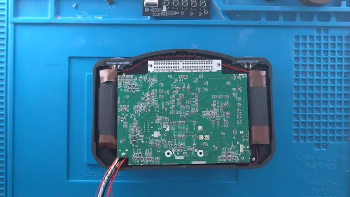
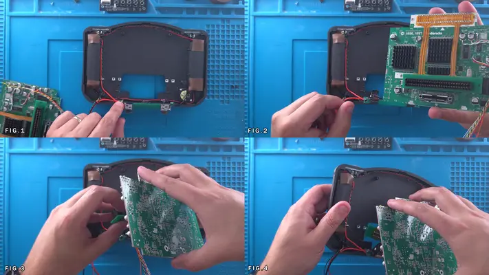
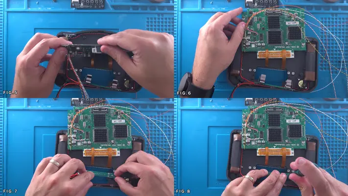
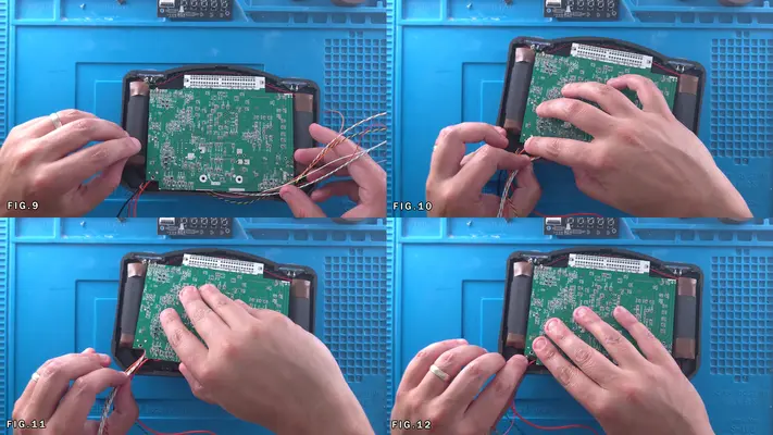
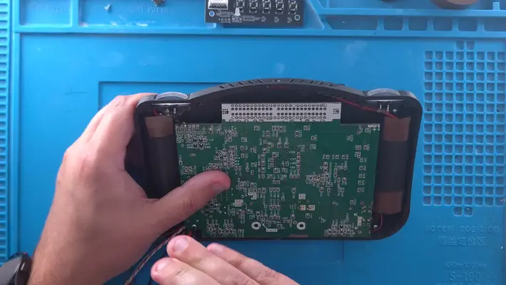
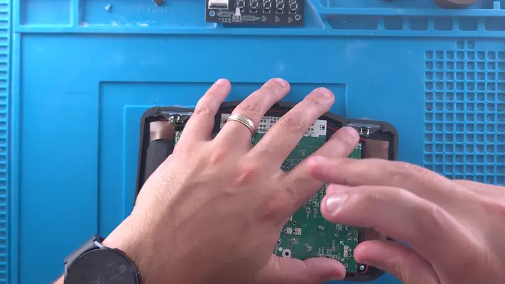
Mounting The Cart Slot and Cart Brackets
STEP SUMMARY
This step can be a bit tricky but is pretty straight-forward for the most part. The cart slot brackets that we prepared earlier do their job well, but can be a little tight to install if you don't do it right. At the same time, we'll also be adding the 3rd battery and putting the jumper pak back in before closing it up with the Cart Cover in the step after.
DIFFICULTY - MODERATE
TOOLS NEEDED
- P2 PHILLIPS SCREW DRIVER
- MULTIMETER
MATERIALS NEEDED
- NONE
PARTS NEEDED
- QTY (2) - CART SLOT BRACKETS W/HARDWARE MOUNTED
STEP PROCESS
1. Arrange the brackets so that screws are on the underside of the carts slot as shown in the first pic. 2. Carefully Press-Fit the bracket over the Cart Slot PCB as far as it can go. The holes should all line up that you can see through it. 3. Repeat for the other side. Fig. 1-5
NOTE: Though not shown, you may want to put a bit of electrical tape on the battery terminal near the Cart Slot, or just over the whole Cart Slot back itself. Though there is enough clearance, it is pretty tight so if it makes you feel better, add a bit of tape to either/or.
4. Position the Cart Slot so the brackets line up with the through holes in the Back Face Plate.
5. Begin to turn the screws and they should start to thread into the Sq Nuts below them. Fig 6-9
6. Next we can add the 3rd Battery but before we do that, it's highly recommended to do a polarity check to make sure the battery goes in the correct way. If all was wired correctly, the (+) Positive side of the batter should be pointing to the right. Verify as shown in Fig. 10-13
7. Last we need to put the Jumper Pak back in place. You will notice I trimmed it down a bit, but this is not needed. Make sure it is inserted correctly though, with the pins on the PCB facing the battery. Fig. 15 & 16
PROCEED TO NEXT STEP
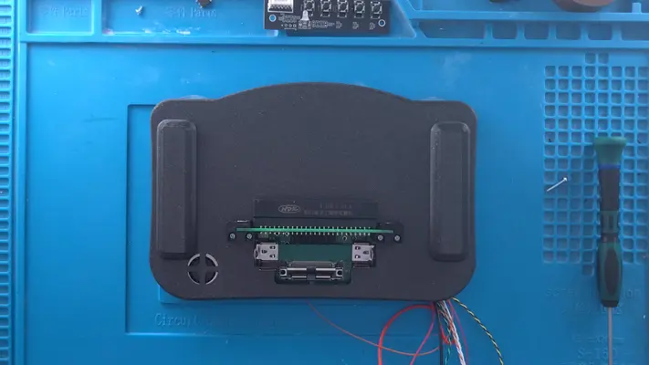
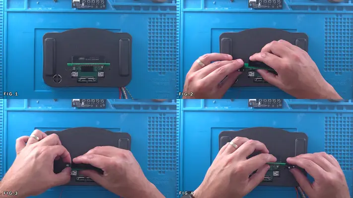
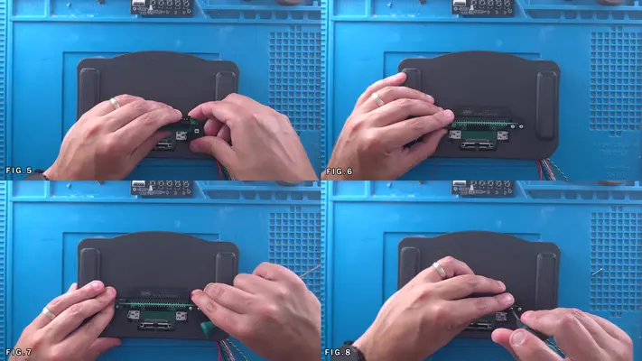
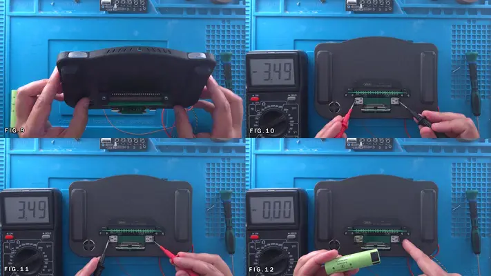
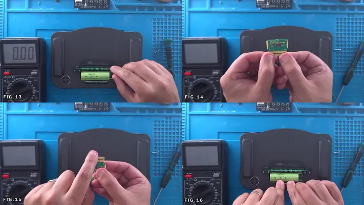
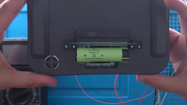
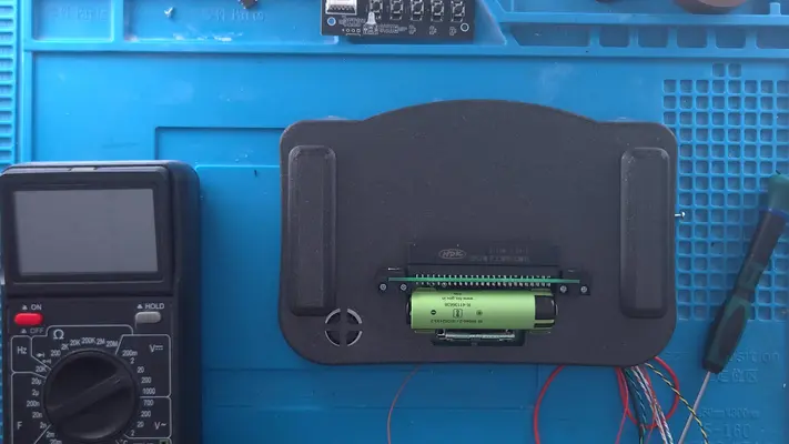
Wiring The Reset & Securing The Cart Cover
STEP SUMMARY A simple two-part step, here we are simply connecting the wires to the tact switch on the cart cover for the reset button and securing that cover to the Back Face Assembly. NOTE: You will notice that the entire Front Face Assembly is shown being fully wired to the Back Face Assembly. This is out of sequence due to getting poor quality images the first time around, so I had to go back and do it again. You should not have that part done up to this point.
DIFFICULTY - EASY
TOOLS NEEDED
- P2 PHILLIPS SCREW DRIVER
- SOLDERING IRON
MATERIALS NEEDED
- SOLDER
- FLUX
PARTS NEEDED
- QTY (1) - CART COVER W/ TACT SWITCH INSTALLED
- QTY (2) - BAG #1/E - #2-56 X 1/2" PPHMS
STEP PROCESS
1. Strip, Tin and Solder the Orange/Black wires and solder them to the legs directly on the tact switch. Fig.1
2. Have the two screws ready and flip the cart cover over, making sure the reset wires tuck back into the enclosure.
3. Push the Cart Cover up so it is tight against the brackets. It should align itself pretty close to where it needs to be.
4. Start the screw in the hole as shown in Fig. 6 and gently press it until you feel it go through the bracket.
5. Tighten down with the screw driver and then repeat the step for the other side.
PROCEED TO NEXT STEP
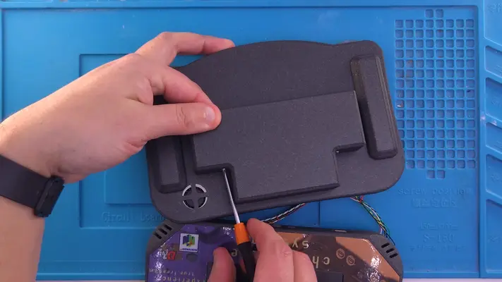
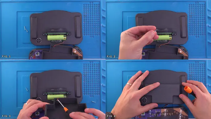
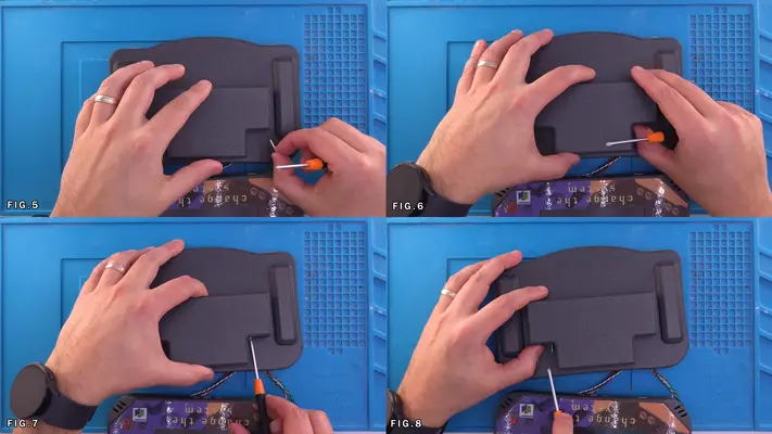
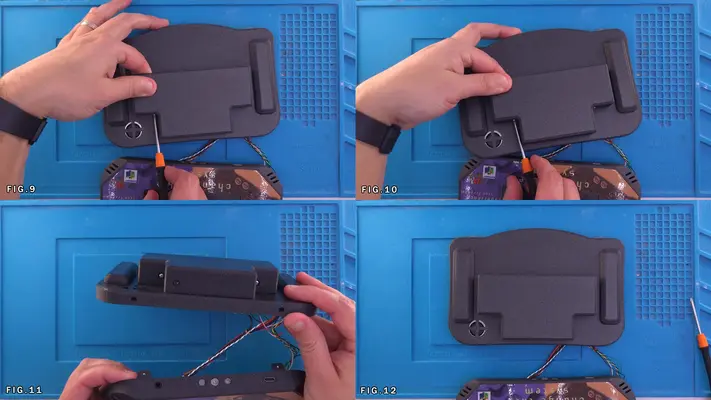
PART XI - WIRING CASE HALVES TOGETHER
SECTION SUMMARY
These next few steps connect the final puzzle pieces together and with just a little bit of luck, you will soon have a working and playable Portable Nintendo 64 in your hands!
In these steps we will be connecting:
- Player 1 Data
- Z Buttons
- Video Line
- Audio Left & Right
- Battery +
- 5V Power
- 3.3V Power
- Various GND Connections
OVERALL DIFFICULTY - MODERATE
CRITICAL STEP AND/OR SAFETY NOTICE
- REMEMBER THAT WE WILL BE DEALING WITH LIVE CONNECTIONS FROM THE BATTERIES AND BEING SURE TO TAKE CARE AND NOT WIRE THE 3.3V LINE TO 5V OR TO GND IS GOING TO BE CRITICAL.
TAKE YOUR TIME AND DOUBLE CHECK YOUR WIRES BEFORE CONNECTING THEM TO THE MAIN MOTHERBOARD!
BACK TO TABLE OF CONTENTS
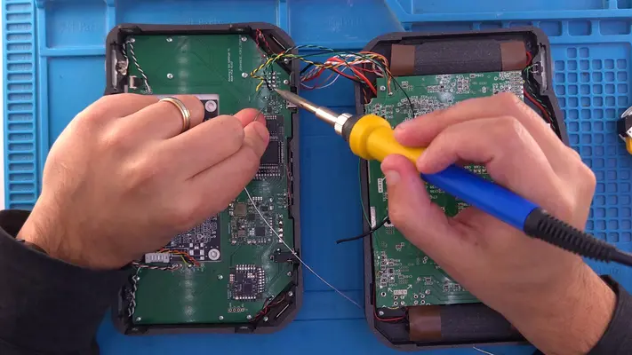
Connecting Case Halves Power & Data
STEP SUMMARY
We're on the home stretch and all that's left now is to connect point A to point B in a few more spots and we're nearly done!
DIFFICULTY - EASY
TOOLS NEEDED
- SOLDERING IRON
- NEEDLE NOSE PLIERS
- WIRE STRIPPERS
MATERIALS NEEDED
- FLUX
- HOT GLUE OR GOOP
PARTS NEEDED
- FRONT FACE ASSEMBLY
- BACK FACE ASSEMBLY
STEP PROCESS
1. Locate the pin header vias on the main motherboard as shown in the first image. It's pretty self explanatory but here's the break down of each pin. P1_D = Player 1 Data Line Z = Z Buttons (Both should already be consolidated to one line) GND = Ground Video = Video Output Line from the N64 GND = Ground IR = Audio Right from N64 GND = Ground IL = Audio Left from N64
2. Because I'm right handed, I prefer to solder my wires from left to right, top to bottom. So this starts us at the Player 1 Data pin. Make sure the wire is routed cleanly from the solder point on the N64, across the board to the wire "harness" and then to the main motherboard. Don't just wire straight across like Fig. 1 shows. Keep it clean!
3. Next we have a Ground pin. Technically speaking, we do not need all of these as the whole system is based on a Common Ground, however I find more is better, but more importantly, I try to keep my Signal Ground Lines away from Power Ground Lines. Again, I know it doesn't really matter, but it just makes me feel better. You can wire these up however you want, but if you used the Twisted Wire method, the Video line and the Z line will already have a ground paired with it. I prefer to twist those ends into one and solder to the GND via in between the Z & Video vias. F For the other two grounds, you can just use a couple strands of 30AWG wire and connect them to any ground point away from the power Grounds. Repeat the process for the Audio IL and IR and all your signal lines should be done!
4. Now time for the Power! Locate the 5 Pads labeled 5V, 3V3, GND, B+ and GND. Remember to be careful any time you're dealing with power and making sure the correct wire is going where it's supposed to! Because even though the PMS has protection built in, the N64 does not!
5. If you used the triple wire method, take the Orange, White, White wire that is wired to the Cap on the N64 and the red wire from the fan and solder to the 5V Pad. The Figs are a bit out of sequence as this was the 2nd time I had to wire this one up so it's a bit of a mess but still shows the process.
6. Do the same for the 3.3V line. (Green, White, White) 7. With a strand of 22AWG black wire, connect the GND pad to the N64 directly. Fig.8
8. Connect the RED 22AWG wire that's connected to the + side of the batteries to the B+ Pad
9. Connect the BLACK 22AWG that's connected to the - side of the batteries to the GND Pad right next to it.
10. You're (nearly) DONE! Feel free to do some wire management after everything is soldered in place and make sure there are no loose connections or shorts! 11. Run a quick test with your continuity meter, testing specifically that your 5V and 3.3V lines are not shorted to ground. If you get no beeps, than we're good and we can move on to the next step!
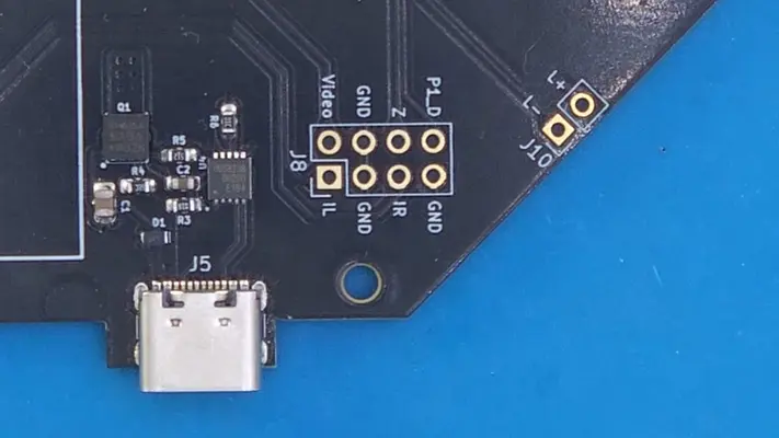
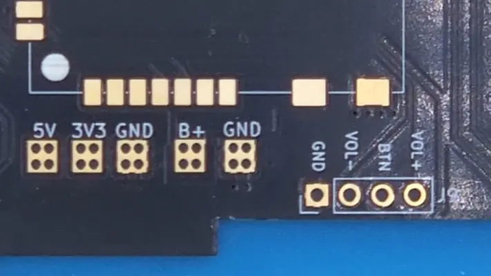
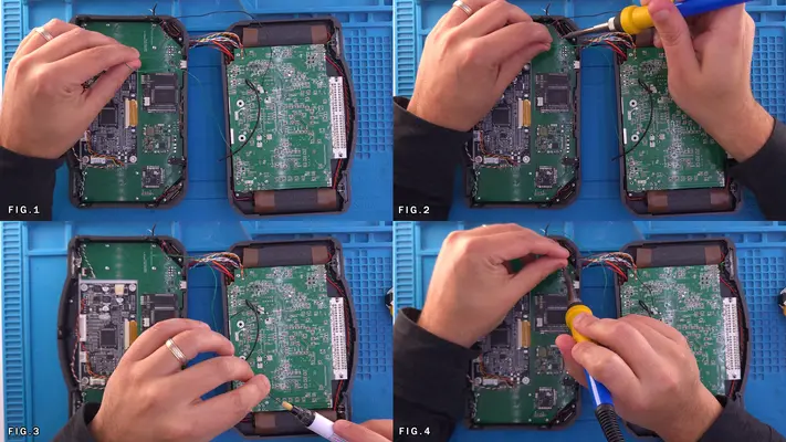
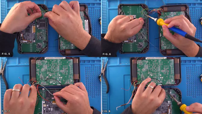
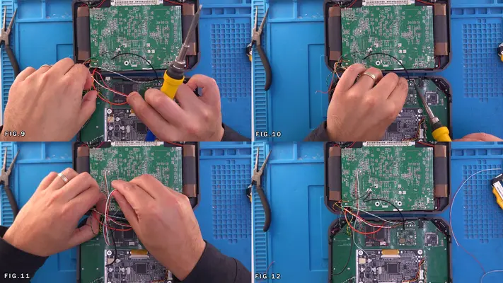
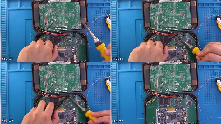
PART XII - TESTING AND TROUBLE SHOOTING
SECTION SUMMARY
The old saying that the last step is usually when the ground falls out from under your feet has the potential to be 100% true in this case as I've found out countless times! However, the whole point of this kit was to mitigate that as much as possible and I'm confident that these issues will be minimal.
OVERALL DIFFICULTY - VARIES
CRITICAL STEP AND/OR SAFETY NOTICE
Remember to again, take your time. If something isn't working and you just can't seem to figure it out, don't get frustrated, just retrace your steps, double check you didn't miss something in the guide and if you still can't, hop on over to the Discord or start a thread on the forums!
BACK TO TABLE OF CONTENTS
Closing Up and Play Testing
STEP SUMMARY
DIFFICULTY -
TOOLS NEEDED
-
-
MATERIALS NEEDED
-
-
-
PARTS NEEDED
-
-
-
STEP PROCESS
Calibrating The Joy Con
The controller board will come to you programmed for the Joy Con, but it will be calibrated to a regular Wii control pot due to my controller programmer/tester rig. While it will work, you'll find the range isn't correct and will affect things like running full speed and so forth.
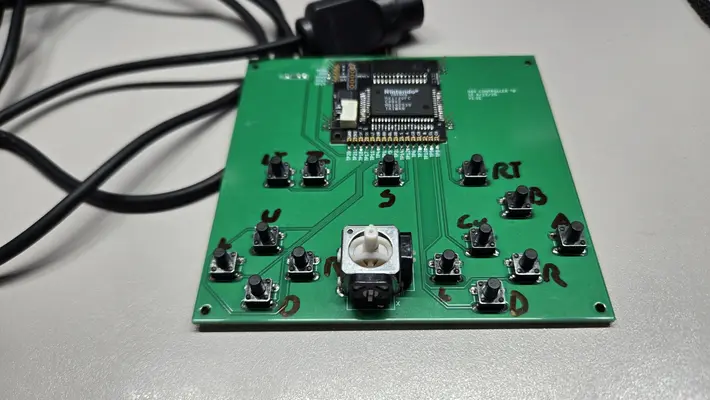
Text Test
STEP SUMMARY DIFFICULTY - TOOLS NEEDED - - MATERIALS NEEDED - - - PARTS NEEDED - - - STEP PROCESS